Cable ODs change late in a project. Every change once meant a new gland order and a stalled panel IATF 16949 1. Multi-layer peelable rubber modules fixed that problem on our production line.
Multi-layer peelable rubber modules adapt to different cable diameters through a step-core body of concentric EPDM layers. Installers peel layers until the inner opening is 0.5–1.5 mm smaller than the cable OD, then a compression wedge squeezes the module against the cable and frame.
That is the short version. The rest of this article walks through the geometry, the sealing physics, the frame compatibility question, and how to test a sample in your own frame before you commit.
How does the step-core peelable layer design let one module fit multiple cable diameters?
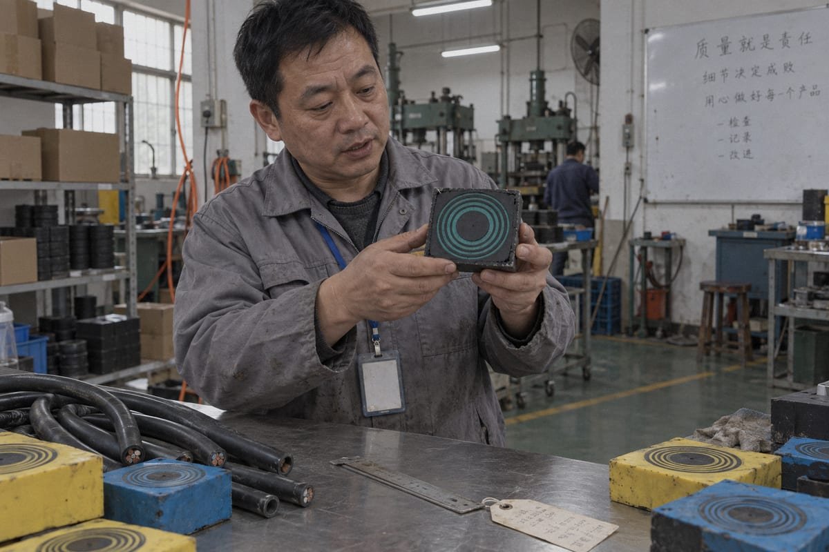
Last month our QC team sectioned a TSC module to check layer bonding. The cut face showed the step-core geometry clearly: a center core wrapped by thin, evenly spaced rings.
The step-core design places a removable center core inside concentric peelable layers. Each layer removed reduces the inner diameter by a fixed step. One module size therefore covers a band of cable ODs, and a family of six sizes typically spans roughly 3 mm to 99 mm.
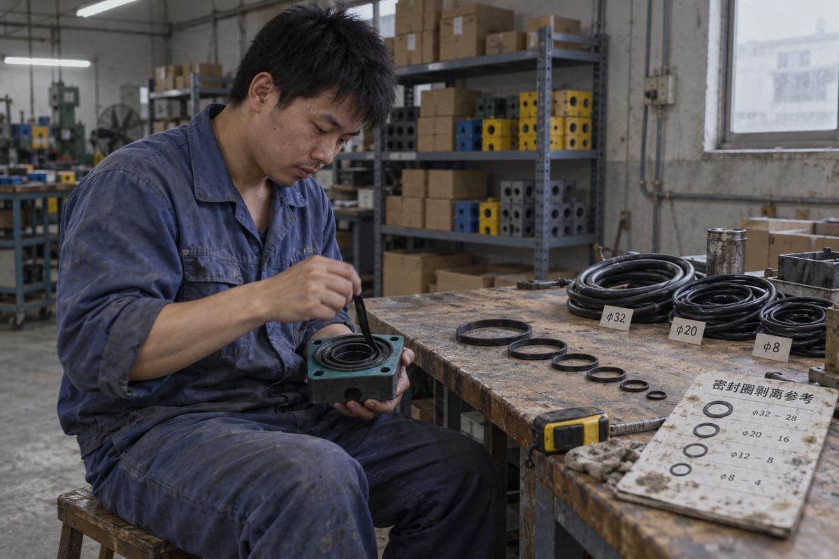
The concept is often sold under the name Multidiameter technology. The idea is simple. A square rubber block is split into two halves. Inside each half sits a solid center core. Around that core, the factory molds concentric rings of halogen-free EPDM rubber 2. The rings are bonded lightly enough to peel by hand, but firmly enough to survive shipping and handling.
Anatomy of a step-core module
When the installer removes the center core, the module has its smallest usable opening. Each ring peeled after that opens the bore by one fixed step. The step size is set by the mold, not by the installer. That is why we call it a step-core design. The fit is predictable, and the same peel count always gives the same inner diameter.
| Module base size (example family) | Typical cable OD band | Layers to peel |
|---|---|---|
| Smallest size | ~3–7 mm | Core only, then 1–2 rings |
| Small | ~7–16 mm | Up to 4 rings |
| Medium | ~16–32 mm | Up to 6 rings |
| Large (e.g. RM60-class) | ~28–54 mm | Up to 8 rings |
| Extra large | ~54–99 mm | Up to 10 rings |
The RM60-class row is a good reference point. One module of that size adapts to cables from 28 mm to 54 mm OD just by removing internal rubber layers. That single part replaces a whole shelf of fixed-size glands.
Why a fixed step matters for your inventory
A modular cable entry built this way cuts SKU count hard. Instead of stocking one gland per cable OD, a panel builder stocks five or six module sizes. Last-minute cable changes on site become a peel operation, not a purchase order. I should be honest about one limit, though. A very wide OD spread still needs different base sizes. "One module fits all" is not literal. It is "one module fits a band," and the bands are wide enough to matter.
Can I confirm these peelable rubber modules will still seal properly after removing layers for smaller cables?
Every peel decision trades interference against insertion effort. Too little interference leaks; too much fights the compression wedge. Our engineers weigh that balance when they write the peel tables.
Yes. Sealing does not depend on how many layers remain. It depends on compression. When the post-peel opening sits 0.5–1.5 mm under the cable OD and a 0.1–1.0 mm gap remains between halves before tightening, the module reaches its rated watertight and gas-tight performance.
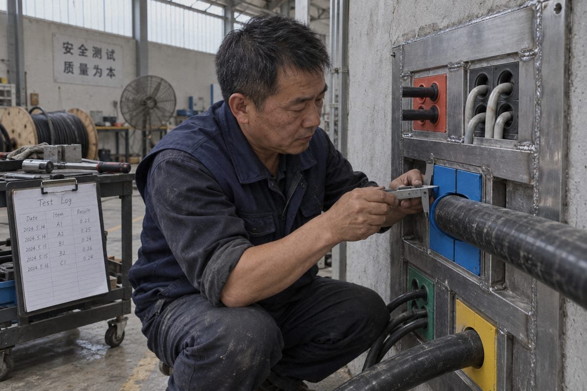
This is the question I hear most from purchasing engineers. It deserves a direct answer with numbers, so here is the mechanism and the checks behind it.
The peel-to-seal workflow, step by step
- Measure the actual cable OD, not the nominal value from the datasheet.
- Peel layers until the module bore is 0.5–1.5 mm smaller than that OD.
- Test-fit the two halves around the cable. A gap of roughly 0.1–1.0 mm should remain between the halves. That gap is the compression reserve.
- Load the module into the transit frame with its stay plates.
- Insert the compression wedge or bolt-type compression unit and tighten to the specified torque.
The final seal is created in step five. The wedge deforms the EPDM rubber radially. Because each remaining layer is a full ring, the deformation is even around the cable. The result is a gas-tight seal that also gives useful strain relief, since the rubber grips the jacket over its full length.
What the test documents show
Our TSC and TSR sealing modules are tested for watertight and gas-tight performance across 0.01–0.4 MPa, and for IP68 ingress protection. Some buyers only specify IP67 ingress protection 3, which the same module clears with margin. Fire-rated seals are tested to A-0 and A-60. All of these results were achieved on modules with layers removed, because that is how modules are used in the field. We supply the test documents on request.
| Installation fault | What happens | How to fix it |
|---|---|---|
| Under-peeling (bore too small) | Halves will not close; wedge over-stressed | Peel one more layer, re-check gap |
| Over-peeling (bore too large) | No interference; leak path along jacket | Replace module or add a size down |
| No gap between halves | Rubber cannot compress further | Peel one layer to restore reserve |
| Uneven wedge torque | One side seals, other weeps | Re-torque evenly; check stay plate seating |
I will raise the honest objection here. Installation quality does depend on correct peeling. That is a real trade-off against a fixed gland. We handle it with printed peel guides on each module and clear torque values, so an electrician can get it right on the first try.
Are these multi-layer modules dimensionally compatible with the 120-frame system I already use?
A sourcing engineer at a BESS container builder sent us a frame drawing and asked whether our TSC modules fit without touching the cutout. We answered with a cross-reference table.
Yes. Our TSC square modules and TSR round assemblies are built to common 120-frame dimensions, so they drop into existing transit frame cutouts as a second source. We supply a model cross-reference table mapping your current part numbers to DEWIN equivalents, plus CAD/STEP files for verification.

Compatibility is not a slogan. It is a list of dimensions that either match or do not. Here is what we actually compare when a buyer sends a drawing.
What dimensional compatibility means in practice
A 120-frame cable sealing system is defined by a packing width of 120 mm across the opening. Modules of different heights stack inside that width. Stay plates sit between rows. The compression unit fills the remaining height at the top. For a drop-in replacement, four things must line up: module footprint, module height steps, stay plate thickness, and the stack height the compression unit needs to reach its working range.
| Compatibility checkpoint | What we compare | What we provide |
|---|---|---|
| Module footprint | 120 mm packing width, depth of frame | Dimensioned drawings, STEP files |
| Module height steps | Standard height increments per module size | Cross-reference table by size |
| Stay plate thickness | Spacer height between rows | Matching stay plates from stock |
| Compression unit range | Total stack height and residual gap | Compression wedge sized to frame |
| Part number mapping | Existing model → DEWIN model | Written cross-reference sheet |
Why this matters more than the price alone
Some engineers prefer to stay with fixed-diameter glands, or with their incumbent module brand, because qualification is simpler. I understand that. Our answer is not just the 40–60% lower cost. It is that the qualification work is already done on our side. Our factory runs ISO 9001 4 and IATF 16949 systems and is BV-approved. We hold 38+ granted patents on our sealing designs. When a module drops into your existing frame and comes with test documents, the qualification effort on your side is a fit check and a document review, not a redesign.
If your frame is not a standard 120 type, our in-house mold shop makes custom module sizes. That is the same tooling capability we use for private-label production. The point is that compatibility is verified with drawings and samples, not promised in a brochure.
How can I get a free validation sample to test peelable module performance before switching suppliers?
We learned early that a spec sheet never closes a second-source qualification. A module in the buyer's own frame does. So we built a free sample program around that lesson.
Send us your current module part number, cable OD list, and frame drawing. We match a DEWIN equivalent from our cross-reference table and ship a free validation sample with test documents, CAD/STEP files, and installation guidance so you can verify fit and sealing in your own frame.
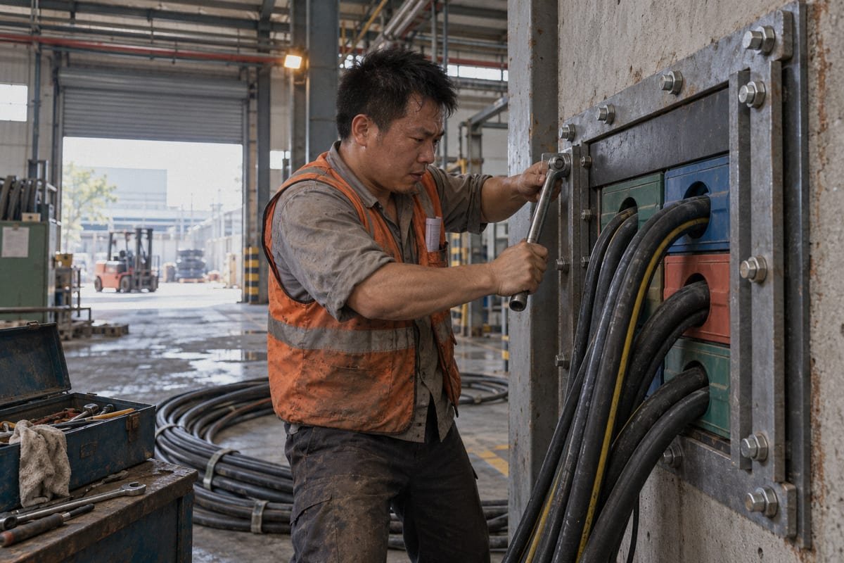
The sample process is short, but each step has a purpose. I want the sample to answer your questions, not create new ones. This is how we run it from our export desk in Shaanxi, with production in Shandong and Hunan feeding the sample stock.
The validation sample process
| Step | What you do | What we do |
|---|---|---|
| 1. Request | Send part number, cable OD list, frame type | Confirm DEWIN equivalent from cross-reference |
| 2. Documents first | Review test reports and STEP files | Send IP68, 0.01–0.4 MPa, A-0/A-60 documents |
| 3. Sample shipment | Receive module, stay plate, wedge as needed | Ship free sample with peel guide and torque values |
| 4. Fit test | Install in your existing 120-frame | English technical support during install |
| 5. Seal test | Pressure or water test per your procedure | Compare results with our factory data |
| 6. Decision | Approve as qualified second source | Set up private label and spare module supply |
What to test on the sample
Test what matters to your product. For a BESS container or modular data center, that usually means fit in the frame, peel behavior on your real cable OD, and an ingress test. Check the gap between halves before compression. Check that the wedge reaches its working range with your stay plate stack. If your application needs fire-rated seals, test against the A-0 or A-60 configuration we document, not a generic setup.
I also suggest one practical test that buyers often skip. Remove the wedge after the seal test, swap one cable for a different OD, re-peel, and re-compress. That tells you how the module behaves during a future cable change, which is the real reason to choose peelable modules over compound seals.
After the sample passes
Once you approve the sample, we handle the rest as a long-term supply partner. Private-label marking, export documentation 5, and fast delivery of spare sealing modules are all in-house. The goal is a qualified second source that lowers your component cost without lowering your certification level or your lead-time confidence.
Conclusion
Cable diameters will keep changing. Fixed glands turn each change into a delay. Peelable step-core EPDM modules absorb the change, seal reliably, and drop into your 120-frame at lower cost.
Footnotes
1. Official oversight body for the global automotive quality management standard. ↩︎
2. Detailed technical information on the properties and applications of EPDM rubber. ↩︎
3. International body responsible for standards on electrical equipment ingress protection ratings. ↩︎
4. Official website for the international standard for quality management systems. ↩︎
5. Official US government resource for international trade and export compliance documentation. ↩︎



 English
  Español de México
  Deutsch
  Français
  العربية
  Русский