
Every month our factory receives cutout sketches for multi cable transit opening sizes that quote the flange, not the aperture IATF 16949 1. Installs stall. Sizing from the aperture fixes that.
Multi cable transit opening sizes must match the frame’s internal aperture plus the supplier’s installation tolerance, typically 5 mm on all sides, not the outer flange. Then confirm each cable’s actual outside diameter, select module sizes, and reserve at least 30% spare packing space before ordering.
That is the short answer. The long answer covers four questions our engineering team gets asked most often. I will walk through each one below, with the numbers we actually use on our production drawings.
كيف يمكنني التحقق من أبعاد فتحة الإطار الموجودة لدي قبل طلب وحدة MCT بديلة؟
A حاوية BESS 2 builder once sent us a drawing marked 130 × 130 mm. Our QC team measured their sample frame. The aperture was actually 120 × 120 mm.
Verify a frame cutout by measuring the internal aperture width and height with calipers, not the flange, then measure frame depth, bolt pattern, and wall opening clearance. Compare those figures with the supplier's sealing module dimensions and cross-reference table before ordering a replacement MCT module.

The mistake in that story is the most common one I see. The flange covers the wall. The aperture holds the modules. Those are two different numbers, and only one of them decides which sealing module dimensions will fit.
Aperture, cutout, and flange: three numbers, three jobs
| البعد | What it describes | Who needs it | Common error |
|---|---|---|---|
| Aperture (window) | Internal packing space where modules sit | Module selection, MCT fill ratio | Quoting it as the wall cutout |
| Structural cutout | Hole in wall, deck, or bulkhead | Fabricator, welder | Cutting it to the flange size |
| Flange (outer) | Plate that covers the structure and takes bolts or welds | Mounting only | Using it to select modules |
One installation guide I keep on my desk states that the structure opening must be 5 mm wider than the frame's inside dimensions on all sides. That clearance lets the frame seat without forcing. If you cut to the flange instead, you get a hole with nothing to weld against.
A four-step field measurement routine
- Measure the clear aperture width and height at two points each. Record the smaller value.
- Measure frame depth and note the wall thickness behind it.
- Count the bolt holes or weld edges and record their spacing.
- Subtract the height reserved for the مجموعة إسفين ضغط and the cumulative thickness of every stayplate installation. What remains is your true packing height.
Step four is where many schedules go wrong. A frame with a 120.5 mm wide filling space may list a nominal height, but part of that height is reserved for final sealing. The rubber never gets it.
When we receive those four measurements, we check them against our cross-reference table, existing model to DEWIN model, and send a free validation sample. Our TSC square modules are built to the common 120-frame standard, so if your aperture measures 120 mm wide, the sample should drop straight in. If it does not, we want to know before you order a container set, not after.
What sizing mistakes should I avoid when cross-referencing my current transit frame model to a new supplier?
There is a real tension we weigh on every cross-reference request: match the packing space exactly, or match the cable schedule. The two are not always the same thing.
Avoid these cross-referencing mistakes: assuming all brands share the same window heights, matching only cable count instead of frame packing space, ignoring compression wedge and stayplate thickness, skipping EMC sleeve width, and trusting nominal conductor size instead of measured cable outside diameter.
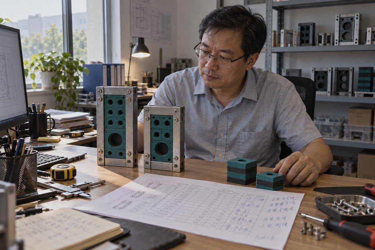
I will be direct about an objection I hear from purchasing engineers in Europe. They ask whether a universal sizing rule exists across brands. It does not. Most systems standardize the width around 120 mm. Heights and internal packing rules vary by product family. So a cross-reference is a dimensional check, not a name swap.
The seven mistakes, ranked by how often they reach our inbox
| Rank | Mistake | Why it hurts | الإصلاح |
|---|---|---|---|
| 1 | Using flange size as the cutout | Frame will not seat, or hole is too large to weld | Size from aperture plus 5 mm clearance |
| 2 | Sizing by cable count only | Cables fit on paper but not in the window geometry | Calculate packing space per row |
| 3 | Ignoring wedge and stayplate height | Last row does not compress | Subtract sealing reserve and stayplate stack |
| 4 | Assuming identical heights across brands | Module rows misalign | Compare window tables side by side |
| 5 | Forgetting EMC earthing sleeves | Sleeves reduce horizontal packing width | Add sleeve width to the row sum |
| 6 | Measuring nominal conductor size | Jacket OD is what the module seals | Measure actual OD with calipers |
| 7 | Mixing service classes without segregation | Later redesign to separate power from telecom | Group cables before selecting the frame |
Why standard window sizes still need checking
Product listings show common packing spaces such as 60 × 120 mm, 120 × 120 mm, 60 × 180 mm, 120 × 180 mm, and 60 × 240 mm. Those figures look interchangeable. They are not. One supplier's 120 × 180 mm frame may reserve a different sealing height than another's. That is exactly why we publish the internal aperture and the external dimension separately on our datasheets. Explicit documentation of aperture versus external size is the detail I would look for on any datasheet before you sign a purchase order.
There is a second objection worth answering. Modular frames simplify procurement, but some buyers argue a custom size fits an unusual cable mix better. Both are right in different projects. Our position is simple: use the 120-standard frame where it fits, because it keeps second sourcing easy. Where it does not fit, our in-house mold shop cuts custom sealing module dimensions, and we tell you which path you are on before quoting.
Can I confirm module-to-frame compatibility using CAD or STEP files before committing to a bulk order?
One lesson cost us a re-shipment early on: a STEP file that clears in CAD can still clash on site, because the model shows uncompressed rubber.
Yes. Request native STEP files of both the frame and each sealing module, overlay them in your CAD assembly, and check aperture fit, stayplate stack height, and compression wedge kit travel. Then validate the digital result with a free physical sample before placing a bulk order.
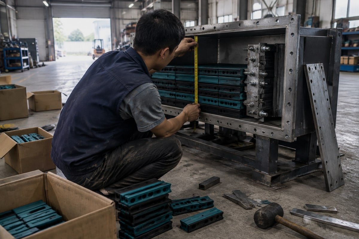
That re-shipment taught our engineering team to treat CAD as a screening tool, not a final gate. Digital clearance is necessary. It is not sufficient. Here is how we split the job today.
What a STEP file can and cannot prove
| تحقق | CAD or STEP file | Physical sample |
|---|---|---|
| Aperture width and height match | نعم | Confirms |
| Bolt pattern and frame depth | نعم | Confirms |
| Stayplate stack height across rows | Yes, if modeled | Confirms |
| As-compressed module state | No, unless supplier models it | نعم |
| Wedge travel and torque behavior | لا | نعم |
| Elastomer swelling in chemical or offshore service | لا | Only over time |
| Thermal creep of high-voltage power cables | لا | Partially |
Generic CAD blocks are the trap. Many libraries show modules at their free, uncompressed size. After the compression wedge kit is torqued, the EPDM spreads sideways and shortens. If your drawing packs the window to 100% using free-state blocks, the real assembly will not close. This is one of the reasons we recommend a spare capacity baseline of at least 30%, even before you think about future cables.
Our validation sequence for a bulk order
- You send the existing frame model number, or your aperture measurements from the routine above.
- We return the cross-reference match and STEP files for the frame, TSC square modules, TSR round assemblies, and stayplates.
- Your team overlays the files and flags any clash.
- We ship a free validation sample set for the exact module mix.
- You compress it in a real frame and check the final row height.
- Only then do we release the production lot.
Two environmental points deserve extra tolerance. Offshore and chemical plants can change elastomer volume over years, so a tightly packed frame may lose seal margin. High-voltage power cables also expand under load and press on the frame. Our halogen-free EPDM is tested for watertight and gas-tight performance between 0.01 and 0.4 MPa, and we can share those test documents. But no test sheet replaces leaving room in the window.
Why does my cable diameter range matter when selecting the correct MCT module size for my frame?
A sourcing manager in Germany asked us why his 4×95 mm² cables would not fit the modules his schedule specified. The schedule listed conductor size, never the jacket.
Cable diameter range matters because each MCT module seals only cables whose measured outside diameter falls inside its step-core range. Too small leaks under pressure; too large will not compress. Correct cable diameter measurement drives module size, MCT fill ratio, and spare capacity planning.
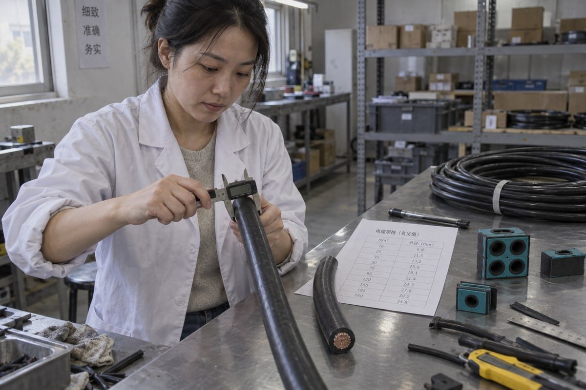
That German schedule is typical. Electrical designers think in conductor cross-section. Cable penetration seals think in jacket diameter. The two numbers can differ by a wide margin between manufacturers, and the jacket is what the rubber grips.
How we measure before we recommend a module
لدينا تصميم القلب المتدرج lets one module size adapt to a range of diameters. You peel layers until the core matches the cable. That flexibility is useful, but it does not remove the need for a real measurement. We ask for three things per cable type.
- الـ outside diameter measured with calipers at two points 90 degrees apart, to catch jacket ovality.
- The cable maker's diameter tolerance, since a plus or minus figure can push a cable across a module boundary.
- The service class, so power, control, and telecom cables can be segregated before we lay out the frame.
From cable list to frame choice
| الخطوة | Input | Output | Sizing rule |
|---|---|---|---|
| 1 | Full cable schedule | Cable list with measured OD | Never use nominal conductor size |
| 2 | Grouped by service class | Rows per class | Keep power away from telecom |
| 3 | Module range table | Module size per cable | OD must sit inside the step-core range |
| 4 | Row widths summed | Required window width | Compare with 120 mm standard width |
| 5 | Rows plus stayplates plus wedge | Required window height | Subtract sealing reserve |
| 6 | تخطيط السعة الاحتياطية | Final frame size | Minimum 30%, up to 100% for growth |
Step six raises the cost objection I hear most. A larger frame means a larger structural hole and more steel. A tighter frame saves footprint but raises retrofit risk. I do not pretend the trade-off disappears. But for a BESS container or modular data center that will be re-cabled within its service life, a 30% spare margin is cheap compared with cutting a second aperture in a sealed enclosure. Some of our EPC customers deliberately design for 100% growth on power rows.
Fill ratio also governs performance claims. Our modules carry an IP68 ingress protection rating 3 and meet A-0 and A-60 fire class requirements, verified under ISO 9001 4 and IATF 16949 systems at a BV-approved factory. Those ratings assume a correctly compressed frame. fire class requirements 5 An overfilled window, or a cable sealed in the wrong module range, is no longer the tested configuration. So the diameter range is not a detail for later. It is where every downstream number begins.
الخلاصة
Wrong multi cable transit opening sizes cost weeks. Measure the aperture, add 5 mm, size from cable OD, keep 30% spare, and validate with a sample before you commit.
الحواشي
1. Official site for the automotive quality management standard cited for the product’s manufacturing verification. ↩︎
2. Provides context on battery energy storage systems (BESS) mentioned as a primary application for cable transits. ↩︎
3. Official explanation of the ingress protection standards used to certify the sealing performance of the modules. ↩︎
4. Official page for the quality management standard used to verify the factory’s production systems. ↩︎
5. Authoritative source for maritime fire safety standards, including the A-60 fire class mentioned in the text. ↩︎



 English
 Español de México
 Deutsch
 Français
 العربية
 Русский