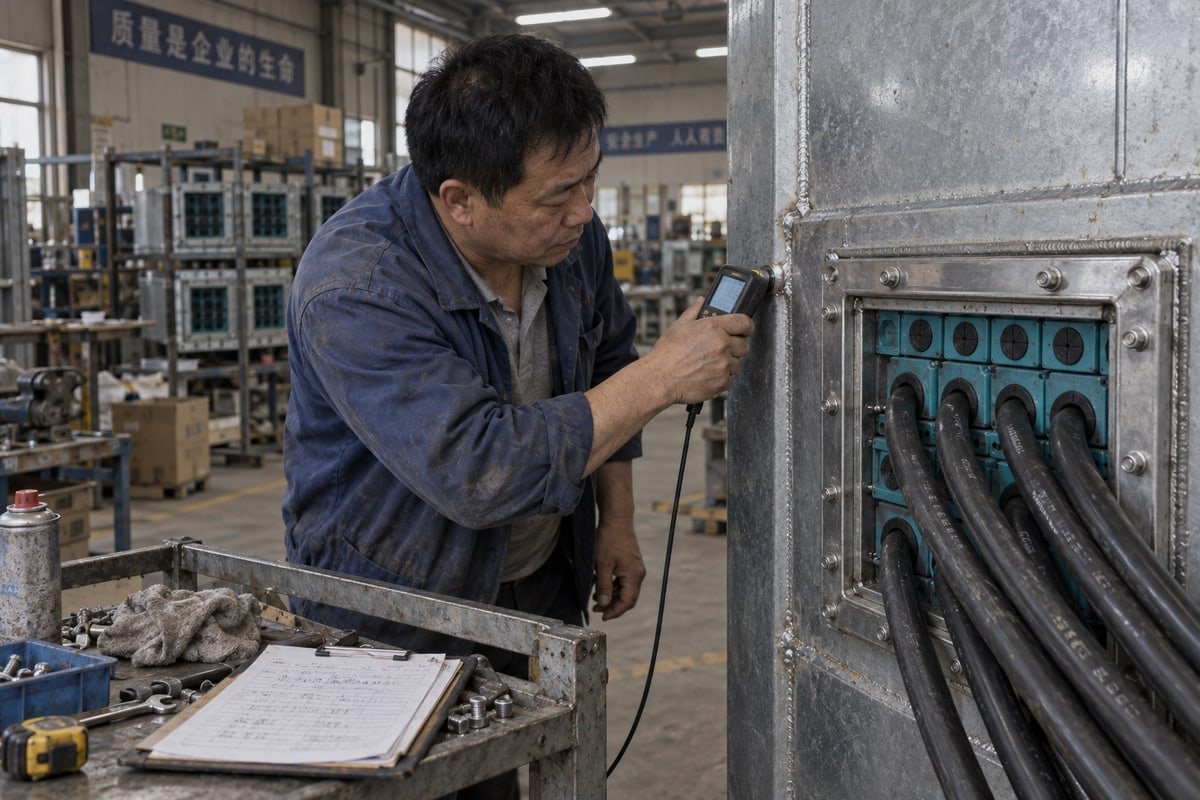
Our engineers see the same gap on many seismic-rated e-house inquiries 1: frame load and weld specs get checked last, after cutouts exist. Then one missing WPS stalls the whole module.
To verify frame load and weld specs for seismic-rated e-houses, request the project seismic loads, the vendor’s frame load limits, WPS/PQR to EN ISO 5817 Class C or AWS D1.1, Material Test Reports, dimensional drawings against your 120-frame standard, and NDT plus test reports before ordering.
That is the short version. The longer version matters more. A cable transit in a seismic zone 2 is not a sealing accessory. It is a small structural connection that sits in the load path between heavy cables and the e-house wall. Below, I walk through the four questions our customers ask most often, and I show what evidence actually closes each one.
How can I confirm the frame's load rating matches my seismic design requirements before ordering?
A sourcing manager in the Netherlands once sent us a full seismic spectrum for his BESS container but no cable mass list. We could not size anything from that alone.
Confirm frame load rating by obtaining the project structural engineer's seismic zone requirements and design accelerations, listing total cable mass and fill per frame, then comparing both against the vendor's published static and dynamic load limits, with a written calculation covering frame, welds, and substrate together.
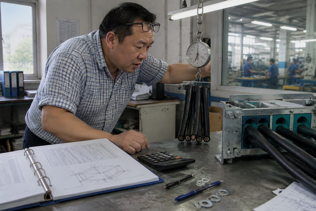
The first thing I ask a buyer to do is forget the product for a moment. Think about the load path instead. Cable weight enters the compression modules. The modules press on the frame. The frame passes everything through its welds into the wall plate, bulkhead, or skid member. Under ground acceleration, that whole chain is shaken sideways and up and down at the same time. The weakest link fails first. In our experience, that link is rarely the rubber module. It is the weld, the parent steel, or a thin panel skin nobody checked.
What loads does an MCT frame actually carry?
| Load type | Source | Why it matters in a seismic e-house |
|---|---|---|
| Dead load | Mass of cables, modules, stay plates, compression units | Sets the baseline stress on frame and welds |
| Seismic lateral load | Design acceleration multiplied by cable and frame mass | Amplifies stress at frame corners and weld toes |
| Vibration | Transformers, HVAC, inverters inside the e-house | Repeated cycles can grow small weld defects |
| Thermal cycling | Day-night temperature swings on container walls | Loosens compression, changes module preload |
| Accidental load | Technicians stepping on cable bundles, tools dropped | Point loads the datasheet never assumes |
| Future cable additions | Spare capacity filled years later | Raises dead load and seismic demand after qualification |
The last row deserves attention. Owners now plan spare capacity in the cable sealing system so later cables can be added without a new penetration. That is good practice. But extra cables add mass, and mass drives seismic force. When we quote a frame for a modular substation design, we ask the buyer to state the planned future fill, not just the day-one fill. Then the load check covers the whole asset life.
Resolving the "it is certified, so we are done" objection
Some buyers tell me the transit has a type approval 3, so the load question is closed. I push back on that. Approvals are valid only inside a defined configuration: a stated frame size, a stated fill, a stated mounting, and a stated test rig. Your e-house wall is not that rig. If the wall skin is thinner, the corner welds are shorter, or the fill is heavier, the approval no longer describes your installation. This is why I recommend a project-specific structural integrity analysis, ideally an FEA that models the frame inside the real wall thickness. It also lets the engineer check the resonant frequency of the loaded frame against the e-house response spectrum, so the assembly does not amplify at the same frequency the building does.
What weld specifications and documentation should I request to verify structural integrity for seismic applications?
During a weld inspection on our Shandong line last year, a corner tack looked fine to the eye. Dye penetrant showed a hairline crack. That frame never shipped.
Request the WPS and PQR qualified to AWS D1.1 or ISO 15614-1, welder qualifications, Material Test Reports for frame steel and consumables, the weld quality class (EN ISO 5817 Class C minimum), weld size and continuity drawings, and post-weld NDT reports for every corner joint.

Weld paperwork looks boring until a frame is halfway through fabrication and the structural engineer rejects the joint detail. Then it becomes the most expensive paper on the project. So I treat frame load and weld specs as one package. The frame drawing tells me the geometry. The weld documents tell me whether that geometry will hold.
Which standards and quality classes apply to MCT frame welds?
The transit industry has a clear baseline here. Mild steel and stainless steel frames are welded to EN ISO 5817 4, minimum Class C. Aluminum frames are welded to EN ISO 10042, minimum Class C. Typical welding guidance also calls for tack welds of 15–20 mm at each corner and at the center of each flange opening before the full run, using MIG/MAG or TIG. On a project with an American design basis, the structural engineer may instead expect AWS D1.1 structural welding procedures 5, plus toughness data for the filler, because seismic connection practice puts weight on ductile weld metal that will not crack under reversed loading.
| Document | What it proves | What it does not prove |
|---|---|---|
| WPS | The intended process, parameters, and joint design | That the welder actually followed it |
| PQR | The WPS produced sound welds in a qualification test | Performance on a different thickness or material |
| Welder qualification | The person can weld this process and position | Weld quality on a specific frame |
| Material Test Reports | Frame steel grade, e.g. S235JR or 316L, and consumable chemistry | Correct heat input or fit-up during welding |
| NDT report | Surface or subsurface soundness of the tested joints | Anything about joints that were not tested |
| Frame weld drawing | Weld type, size, continuous or intermittent, seal weld location | Adequacy for the seismic load unless a calculation is attached |
Factory welding versus site welding
Here is a real trade-off I discuss with EPC teams. Factory welding, whether at our plant or at the e-house fabricator, gives controlled fit-up, stable parameters, and easy access for non-destructive testing on all four corners. Site welding is sometimes unavoidable on retrofits. It brings tight access, variable preheat, and welds done at awkward angles. If site welding is the only option, I recommend more hold points, not fewer: fit-up inspection, visual inspection after tacks, and dye penetrant or magnetic particle inspection on every corner after the final pass. Some contractors prefer a standard weld detail to keep things simple. Structural engineers usually want the detail confirmed by calculation for the project. In a seismic zone, the engineer is right. Local stress at a frame corner can run far above the average, and that is exactly where a brittle detail shows itself.
Do not forget the substrate
A perfect weld on a 2 mm container skin is still a failure mode. Ask for the host steel thickness and edge distances. Ask whether the wall panel, stiffener, or skid rail has been checked for the reaction the frame delivers. In our drawings we always flag the recommended minimum plate thickness so the e-house builder can coordinate this early.
How do I cross-check DEWIN's frame dimensions against my existing 120-frame standard to ensure a true drop-in fit?
Every time we tool a new frame size, we weigh tighter tolerance against mold cost. For 120-frame drop-in work, we always pick tolerance. Fit failures cost more.
Cross-check DEWIN frame dimensions by requesting the model cross-reference table, STEP or CAD files, and a free validation sample, then measuring opening width, height, flange thickness, bolt pattern, and packing depth against your existing 120-frame drawing before approving a drop-in replacement.
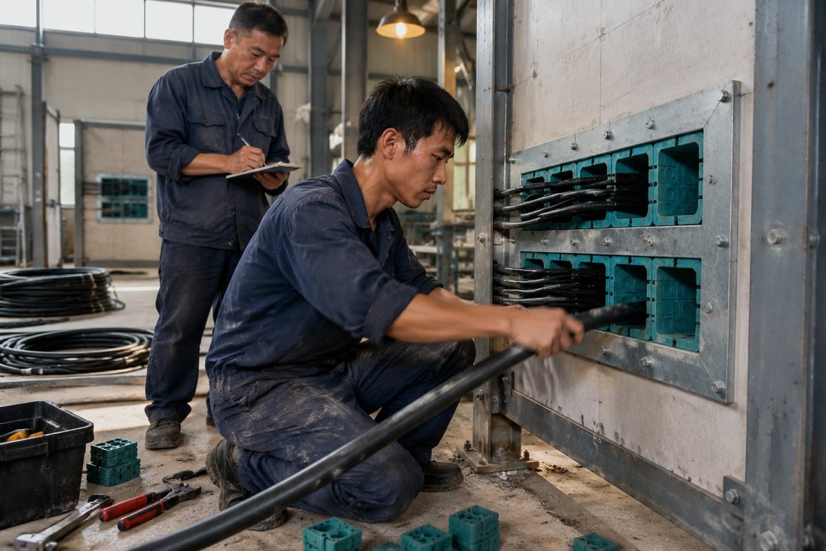
Dimensional compatibility is our first differentiator, so I want to be exact about what "drop-in" means and what it does not. It means our TSC square modules, TSR round assemblies, stay plates, and compression units are dimensionally compatible with common 120-frame standards, so they fit the cutouts and frames you already have. It does not mean you should skip verification. A qualified second source earns that status by passing your checks, not by claiming it.
A five-step cross-check we recommend
- Send us your incumbent model numbers. We return a cross-reference table mapping each existing model to the DEWIN model, with the frame series, module count, and cable diameter range per module.
- Request the STEP or CAD file for each frame and module. Overlay it on your existing drawing in your own CAD system. Look at the outer flange, the inner opening, and the packing space depth.
- Ask for a free validation sample of the frame and a small module set. Measure it on your bench with your own gauges. Do not rely on our numbers alone.
- Fit the sample into a spare cutout or a test plate cut to your standard. Check that the stay plates seat, the compression unit reaches full travel, and the modules close around your real cable diameters.
- Record the result as a formal supplier qualification step, with photos and measurements, so procurement and engineering share one file.
What to measure and why
| Dimension | Why it matters for a drop-in fit | Where seismic performance is affected |
|---|---|---|
| Inner opening width and height | Determines module count and fill | Changes cable mass per frame |
| Flange width and thickness | Sets the weld leg length available | Directly drives weld capacity |
| Corner radius and weld prep | Affects fit into existing cutouts | Corners are the highest-stress weld zones |
| Bolt hole pattern (bolted frames) | Reuse of existing drilled plates | Bolt shear under lateral load |
| Packing depth | Compatibility with existing modules and stay plates | Module preload and pull-out resistance |
| Compression unit travel and torque | Correct sealing force on modules | Under- or over-torque distorts the frame |
The torque line matters more than buyers expect. The installation manual should state the compression unit torque. Too little, and modules can creep under repeated shaking. Too much, and a thin frame can bow, which pre-stresses the corner welds before any earthquake happens. Our step-core, halogen-free EPDM modules take up a range of cable diameters within one size, so the buyer has fewer part numbers to manage. But the compression setting still has to match the frame, and we put that value on the drawing for each frame series.
One more point for European buyers who read spec sheets before replying. We provide the cross-reference table, STEP files, and samples at no charge, and our English-speaking engineers answer dimensional questions directly. That is the practical side of being a factory with in-house mold making rather than a trading company.
What test reports or certifications can I request to validate seismic performance before committing to a bulk order?
One lesson stuck with us after our first BV factory audit: a certificate only means something inside its stated scope. Seismic claims deserve the same reading.
Request IEEE 693 seismic qualification reports or project-specific FEA, third-party type approvals from DNV or UL showing the tested configuration, firestop certification (A-0/A-60), IP68 and pressure test reports, Factory Acceptance Testing records, and stated limits, then verify each matches your exact frame and fill.

Buyers often mix four different performance claims into one word: "rated." Fire, ingress, gas tightness, and seismic behavior are separate tests with separate scopes. I encourage sourcing teams to sort the documents into piles before judging any of them.
Which reports prove what
| Report or certificate | What it validates | Questions to ask about scope |
|---|---|---|
| IEEE 693 standard qualification | Seismic performance of substation equipment and its cable entries | Which performance level? Which frame size and fill? Which mounting? |
| Project-specific FEA or structural analysis | Frame, welds, and substrate under your site accelerations | Was the real wall thickness modeled, or a rigid rig? |
| DNV or UL type approval | Product performance within listed limits, sometimes including blast or seismic | Does the listed configuration match yours? |
| Firestop certification A-0 / A-60 | Fire integrity of the sealed penetration | Tested with which frame material and module fill? |
| IP68 and pressure test reports | Watertight and gas-tight sealing, in our case tested across 0.01–0.4 MPa | Before or after seismic cycling? |
| Pull-out force test | Cable retention under load and vibration | Cable type and compression torque used? |
| Factory Acceptance Testing record | The delivered batch matches the approved design | Which samples were tested and by whom? |
Where DEWIN documents fit, and where your engineer takes over
I want to be direct about scope. Our factory runs ISO 9001 and IATF 16949 systems 6 and is BV-approved. We hold A-0/A-60 fire rating, IP68 ingress protection, and watertight/gas-tight test results from 0.01 to 0.4 MPa, and we share these documents on request. These cover the sealing performance of the cable sealing system. Seismic adequacy of a welded frame in your specific e-house is a structural question tied to your seismic zone requirements. For that, we supply what your structural engineer needs as inputs: frame drawings with weld details, Material Test Reports for the frame steel, module mass data, compression torque values, and validation samples. Your engineer, or a third-party lab, then produces the seismic qualification or FEA for the real configuration. I would rather say this plainly than hand over a brochure that implies more than it proves.
Ask about behavior during and after the event
Some transit vendors market products tested for seismic actions that keep smoke tightness and fire performance during and after shaking. That is a valuable claim. Ask for the test conditions behind it: acceleration level, frame size, fill ratio, and whether the pressure testing protocols were repeated after the seismic run. Also ask about long-term re-compression, sometimes called seismic creep. If the design allows modules to be re-torqued years later, confirm that re-compression does not load the corner welds beyond the original analysis. These questions separate a real qualification from a marketing line.
Fazit
Seismic-rated e-house transits are structural assemblies. Verify loads, welds, dimensions, and test scope as one system, then qualify DEWIN with samples and documents before committing.
Fußnoten
1. Defines the modular electrical houses used to protect critical equipment in industrial and utility sites. ↩︎
2. Provides the standard for seismic design and qualification of substation equipment and cable entries. ↩︎
3. Explains the type approval process for certifying product performance within defined configuration limits. ↩︎
4. Defines the quality levels for imperfections in fusion-welded joints in steel and stainless steel. ↩︎
5. The authoritative structural welding code for steel connections in seismic and industrial applications. ↩︎
6. Official overview of the quality management system standards used to ensure manufacturing consistency. ↩︎


 English
  Español de México
  Deutsch
  Français
  العربية
  Русский