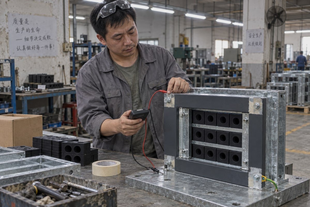
Purchasing engineers ask our factory this weekly: how to balance frame coating and grounding continuity when sourcing MCT IATF 16949 1. Get it wrong, and a corrosion-proof frame becomes an insulator.
Balance frame coating and grounding continuity by coating the MCT frame broadly for corrosion resistance while masking or clearing designated bonding surfaces, keeping internal coating under 100 microns, and verifying electrical continuity with a micro-ohmmeter after installation and after every modification.
That answer sounds simple. In practice, it touches four separate decisions. Let me walk through each one the way we handle it on our own production line and in supplier qualification calls with buyers.
How can I ensure grounding continuity isn't compromised by powder coating on MCT frames?
During a final inspection last year, our QC lead bolted a fully powder-coated frame to a test plate and measured open circuit. The coating looked perfect. That was the problem.
Ensure grounding continuity by masking bonding surfaces before powder coating, keeping any coating inside the frame below 100 microns, using unpainted contact patches at welds and bolt points, and confirming metal-to-metal contact with a resistance measurement rather than a visual check.

Grounding, bonding, and where the path actually runs
First, the terms. Bonding means electrical continuity 2 between metal parts. Grounding means the connection of that bonded metal to earth. An MCT frame is bonded to the bulkhead or enclosure wall. The earth connection is usually made somewhere else on the structure. So the frame only needs a reliable metal-to-metal path to the wall it sits in.
Here is a point many buyers miss. Standard sealing modules are rubber. Our TSC and TSR modules use halogen-free, step-core EPDM. EPDM is an insulator. It does not carry current, and it is not meant to. The safety path runs frame to structure, not through the modules. The EMC path is different. In EMC-grade transits, about 10 mm of outer cable insulation is stripped, the exposed braid is placed in the center of the insert block, and an earth screen or conductive sheet carries current from the braid into the frame. That is a separate specification from a standard cable sealing system, and you should ask for it by name.
Why powder coat breaks the path
Powder coating is an excellent barrier. That is exactly why it is a problem at contact points. Two coated parts bolted together look connected. Electrically, they are not. One installation guide we reference recommends no more than 100 microns of coating inside the frame. Thicker coating makes modules harder to fit but does not compromise sealing. Coating on a bonding surface, however, defeats the earthing and bonding path entirely.
| Finish on contact surface | Conductive at contact? | Corrosion resistance | Required action |
|---|---|---|---|
| Powder coat (epoxy/polyester) | No | High | Mask bonding patches before coating |
| Wet paint | No | Medium | Scrape to bare metal, then protect |
| Hot-dip galvanizing | Yes, but zinc oxide forms | High | Use serrated washers, apply conductive grease |
| Trivalent chromium passivation 3 | Yes | Medium to high | Verify with resistance test |
| Bare AISI 316L stainless | Yes | High | Clean contact area, no coating needed |
What we do on our line
On our galvanized steel frames, we mask the bolt lands and the earth lug pad before any topcoat goes on. We then check each masked patch with a meter before shipping. It is a simple step. It removes the guessing.
What test documents should I request to verify grounding resistance across coated frame surfaces?
A sourcing manager in Germany once returned our fire and IP68 reports with one question: where is the grounding resistance data? That email reshaped our document pack.
Request a coating thickness report, a drawing marking bare bonding surfaces, a contact resistance measurement across the coated frame with instrument and method stated, a fault-current capacity statement for any bonding strap, and the vendor's post-installation continuity test procedure.

The document set that actually proves continuity
Buyers often receive a certificate stack that says nothing about grounding. Fire rating, ingress protection, and pressure tests are essential, but they are sealing documents. Grounding needs its own evidence. This is the list we now prepare when a project asks for it.
| Document | What it must show | Why it matters |
|---|---|---|
| Coating thickness report | Microns per surface, inside frame under 100 | Confirms modules will fit and bonding areas are not over-coated |
| Marked-up frame drawing | Exact location and size of bare contact patches | Installer knows where the earth lug and bolts land |
| Contact resistance measurement | Instrument (micro-ohmmeter 4), test points, milliohm value | Replaces visual inspection with a number |
| Fault-current capacity statement | Conductor cross-section or strap rating | OSHA requires bonding conductors to safely carry fault current |
| Continuity test procedure | Steps for commissioning and after any modification | MSHA guidance calls for periodic retesting of frame grounding |
| EMC test data (if EMC modules used) | Shielding attenuation across frequency | Supports EMI shielding claims, not just safety |
Reading a resistance report critically
A number alone is not enough. Ask three things. What instrument was used? A standard multimeter cannot resolve milliohm values, so the report should name a micro-ohmmeter. Where were the probes placed? A reading from lug to lug on the same bare patch proves nothing. The reading should span the coated frame, from the earth pad to the far mounting bolt. What was the acceptance threshold? Project specs and regulatory bodies set different limits, so the report should state which threshold applied.
What our own pack contains
Our standard documents cover ISO 9001 5 and IATF 16949 systems, BV factory approval, A-0/A-60 fire ratings, IP68 ingress protection, and watertight and gas-tight sealing from 0.01 to 0.4 MPa. Grounding resistance is project-specific, so we measure it on request against the frame drawing you approve. If your installation sits in a hazardous zone and needs ATEX certification, treat that as a separate document request as well. Electromagnetic compatibility (EMC) data is only relevant if you order conductive inserts, so ask for it only when it applies.
Can I specify bare contact points or conductive coatings without sacrificing corrosion protection?
The trade-off we weigh on every custom frame order is simple: more bare metal means better electrical continuity, and more bare metal means more places for rust to start.
Yes. Specify small masked contact patches protected with conductive grease, or use conductive thin-film finishes such as trivalent chromium passivation, or choose AISI 316L stainless frames that need no insulating coat. Each keeps corrosion protection while preserving a low-resistance path.

Three ways to protect the frame and keep the path
Some buyers want maximum coating coverage. Others want the frame left bare at every joint. Both positions are wrong on their own. The workable answer is to coat broadly and leave conductivity only where it is engineered. Here is how the main options compare.
| Strategy | How continuity is kept | Corrosion protection | Best fit |
|---|---|---|---|
| Coated frame plus masked patches | Bare metal at bolt lands and earth pad, sealed with conductive grease after torque | High on body, protected at patches | Galvanized steel frames in BESS containers and switchgear |
| Conductive thin-film finish | Trivalent chromium or conductive primer over full surface | Medium to high | Data center enclosures with many bond points |
| Bare AISI 316L stainless | Whole frame is conductive | Inherent | Marine, offshore, coastal infrastructure |
| Integrated EMC modules | Tin-plated copper earthing strap or earth screen embedded in the module | Depends on frame choice | EMI shielding of screened cables |
Details that decide long-term contact resistance
Three details matter more than the choice of strategy.
First, galvanic pairing. Pick a bonding strap, washer, and lug with an electrochemical potential close to the frame material. A poorly matched pair corrodes at the exact interface you need to stay clean. Contact resistance then rises year by year.
Second, humidity. In marine or humid plant rooms, a bare patch oxidizes. Conductive grease or an anti-seize compound on the patch blocks moisture while keeping the path.
Third, vibration. In compressor rooms and mobile equipment, micro-arcing at a loose bond point erodes the contact. Specify compression units that hold constant mechanical pressure, and use serrated or lock washers at bond points.
Our practical position
For most OEM integrators we serve, a galvanized frame with masked patches gives the best cost-to-performance balance. When a customer specifies stainless, our in-house mold and fabrication team builds it to the same 120-frame cutout, so the drop-in compatibility does not change.
How do I qualify a drop-in MCT frame that meets both coating specs and grounding standards?
We learned early that a drop-in frame can match every 120-frame cutout dimension and still fail commissioning if nobody defined where the earth connection lands.
Qualify a drop-in MCT frame in four steps: confirm dimensional compatibility with a cross-reference table, verify coating specs and masked contact areas on the drawing, test a free validation sample for sealing and continuity, then retest resistance after installation and after any modification.

A four-step qualification process
The steps below are the ones our customers in Europe and the Middle East run when they add us as a second source. Each step produces a document. That paper trail is what protects you later.
-
Dimensional match. Start with the model cross-reference table from existing model to the DEWIN equivalent. Check frame outer dimensions, cutout size, module stack height, and compression unit travel. Ask for CAD or STEP files and overlay them on your existing drawing. If the frame does not drop into the current cutout, stop here.
-
Coating and contact review. Read the coating specification against the frame drawing. Confirm the internal coating limit of 100 microns. Confirm that bolt lands and the earth pad are marked as masked. Confirm the coating type on the rest of the frame matches your corrosion class. If EMC modules are needed, confirm whether the earthing strap or earth screen is integral to the module or must be added in the field. Integral grounding is easier to qualify because it ships tested.
-
Sample validation. We send free validation samples for exactly this step. Fit the sealing modules and compression unit in your own frame cutout. Run your sealing check against IP68 and your required pressure within 0.01 to 0.4 MPa. Then measure resistance across the frame with a micro-ohmmeter and record the value. If your engineering team uses BIM, this is also the point to model the cumulative impedance of the transit at your EMI frequencies of interest.
-
Commissioning and retest. After installation, repeat the resistance measurement across the coated frame. Log it. Then set a rule: any time the transit is opened, a module is replaced, or the frame is re-torqued, the continuity test is repeated. This follows the MSHA logic of retesting after repair or modification, and it keeps the OSHA requirement for fault-current capacity verifiable over the life of the asset.
Signs of a well-engineered second source
A qualified second source does not just match a size. It supplies the cross-reference table, the marked drawing, the coating report, and the sample without being chased. It answers technical questions in English within a working day. It builds custom frame sizes with its own molds when your cutout is non-standard. Cost matters, and a 40 to 60 percent saving against incumbent brands is real. But the saving only counts if certification, compatibility, and continuity all survive the qualification.
Conclusion
Coat the frame, not the contact. Specify masked bonding surfaces, demand resistance data, and qualify each drop-in frame with samples and tests. That is how coating and continuity coexist.
Footnotes
1. Global quality management standard for the automotive industry and manufacturing supply chains. ↩︎
2. OSHA provides definitions and safety standards for electrical continuity and bonding in industrial settings. ↩︎
3. Technical explanation of conductive thin-film finishes used for corrosion protection in metal components. ↩︎
4. Specialized instrument used to measure extremely low electrical resistance in bonding paths. ↩︎
5. International standard for quality management systems used to qualify manufacturing suppliers. ↩︎



 English
  Español de México
  Deutsch
  Français
  العربية
  Русский