
A transit passes inspection, then leaks a year later. On our line, we trace most failures to miscalculated fill rate and compression rate in the qualified multi cable transit installation.
Fill rate is the total cable cross-sectional area divided by the usable transit opening area, expressed as a percentage. Compression rate is the compression unit’s stroke divided by the uncompressed module stack height. A qualified installation keeps both within the type-approved limits stated in the manufacturer’s certificate.
Those two sentences hide a lot of detail. Below, I walk through each calculation, show a worked example, explain what goes wrong outside the limits, and describe how to check your numbers against real test documents.
How do I calculate the correct fill rate for my cable transit module selection?
A sourcing engineer in Europe once sent us a photo of a frame that looked "full" and asked whether it passed. We asked for cable diameters instead.
Measure each cable's outer diameter, calculate its area with πr², sum all areas, and divide by the usable internal area of the frame opening. Multiply by 100 for the percentage. Compare the result to the maximum fill in the type approval, and select modules whose step-core range covers each diameter.
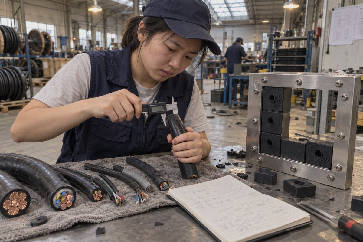
Fill rate is a cross-sectional area ratio. It is not a count of cables, and it is not how crowded the frame looks. The formula is simple, but the inputs need care. I will break it into steps, then show where people go wrong.
Step-by-step worked example
Use the outer diameter of the cable jacket, not the conductor size. Convert diameter to radius, square it, and multiply by π. Then sum the areas and divide by the usable opening. The numbers below are illustrative. They are not a published limit for any product.
| Cable group | Outer diameter (mm) | Radius (mm) | Area per cable (mm²) | Quantity | Group area (mm²) |
|---|---|---|---|---|---|
| Power cables | 22 | 11 | 380.1 | 4 | 1,520.5 |
| Control cables | 14 | 7 | 153.9 | 6 | 923.6 |
| Signal cables | 8 | 4 | 50.3 | 8 | 402.1 |
| Total cable area | 18 | 2,846.2 |
Now take a frame with a usable internal opening of 120 mm × 120 mm, which is 14,400 mm². Divide 2,846.2 by 14,400 and multiply by 100. The fill rate is about 19.8%. That sits well below the 40% cap used by systems aligned with IMO Resolution A.754(18) 1, and below the 50% limit some sealing systems publish. Type approvals from bodies like ABS, DNV, or UL generally cap fill somewhere between 40% and 70%. The exact number belongs to the tested system, so read the certificate.
Cable diameter tolerance matters
Cable jackets are not perfect. Real outer diameter can differ from the datasheet value. We tell buyers to measure a sample at two points and use the larger reading. Our step-core EPDM modules cover a range of diameters within one module size, so small variation is absorbed. Still, the fill calculation should use real measured values, not nominal ones.
Area-based fill versus packing space calculation
In modular systems, there is a second check. The packing space calculation confirms that the chosen sealing module dimensions, stay plates, and compression unit physically fit the frame's packing height. Both checks must pass. A layout can be under the fill limit yet still not fit the frame, or fit the frame yet exceed the approved fill.
One more tension deserves a direct answer. Some buyers push for the highest approved fill to save frame space. Others want a conservative fill. Standards like TIA-569 and IEEE 525 recommend leaving 20% to 25% spare capacity 2 for future cables. My advice is to plan spare capacity from the start. Adding a second frame later costs far more than one larger frame today.
What compression rate should I target to guarantee a watertight and gas-tight seal?
Every compression target we set in our test bay balances two failures. Too little squeeze and water finds a path. Too much and the cable jacket necks.
Target the compression rate stated in the manufacturer's type-approval documentation, not a generic figure. It is calculated as compression unit stroke divided by the uncompressed module stack height. The correct value depends on module material, sealing module dimensions, and cable jacket hardness, and is verified by a water-tight integrity test.
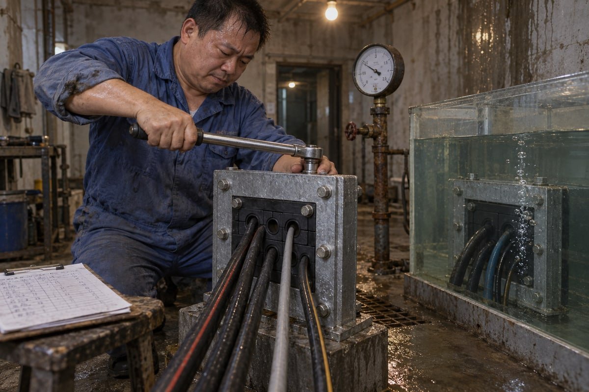
Compression rate is less standardized than fill rate. Public guidance treats it as the percentage reduction in module height after tightening. In practice, the frame has a fixed packing height. The modules, stay plates, and compression unit are stacked inside. When the compression wedge is driven in, it expands and squeezes the elastomeric sealing blocks against the cables and the frame walls.
The formula in practice
The ratio is stroke divided by uncompressed stack height. If your modules stack to 100 mm uncompressed and the wedge stroke is 8 mm, the rate is 8%. The numbers below are illustrative only. Real targets come from the product's test report.
| Scenario | Uncompressed stack height (mm) | Wedge stroke (mm) | Compression rate | Likely result |
|---|---|---|---|---|
| Under-compressed | 100 | 4 | 4% | Leak path along cable jackets |
| Within tested range | 100 | 8 | 8% | Watertight and gas-tight seal |
| Over-compressed | 100 | 14 | 14% | Jacket necking, module distortion |
Compression wedge adjustment is where installers make or lose the seal. Tighten the bolts in steps and check that the wedge expands evenly. Uneven compression loads one side of the stack more than the other. That is also why stay plate placement matters. A stay plate between every row of modules spreads the force across the stack and stops modules from popping out under pressure or blast.
Jacket hardness, creep, and compression set
Three material factors shift the right target. First, the Shore hardness 3 of the cable jacket. A soft PVC jacket deforms more than a hard XLPE jacket at the same force, so the seal pressure that works for one may neck the other. Second, cold flow. Polymer jackets creep over years, and the effective sealing pressure can drop. Third, compression set. The module material must keep its elastic push-back over decades to compensate for that creep.
We chose halogen-free EPDM for our TSC and TSR modules for that reason. EPDM holds its recovery force well and tolerates temperature swings in BESS containers and outdoor switchgear. Our tested sealing range is 0.01 to 0.4 MPa watertight and gas-tight, and the test documents are available on request. Whatever system you use, the target compression rate is the one tied to that system's test report, not a figure copied from another brand.
What happens to my installation if the fill rate or compression rate falls outside the qualified range?
The hardest lesson since we started in 2013: a seal can pass a site pressure check and still be unqualified on paper.
Outside the qualified range, the installation loses its type-approval status. Over-fill leaves too little elastomer to seal or resist fire. Under-compression allows water and gas leakage. Over-compression damages cable jackets and accelerates creep. The result is a seal that may pass today's inspection yet fails certification, warranty, and long-term integrity.

"Qualified" has a precise meaning here. It means the installed configuration matches what the type test proved. That covers maximum fill percentage, permitted cable diameters, frame depth, sealant thickness, and allowable compression. Step outside any one of them and the certificate no longer describes your installation. Nothing may leak on day one. But the fire rating, the pressure rating, and the insurance position all rest on that certificate.
Failure modes by parameter
| Parameter | Out-of-range condition | Immediate effect | Long-term effect |
|---|---|---|---|
| Fill rate | Above approved maximum | Thin elastomer walls, uneven compression | Loss of fire and gas integrity, module pop-out risk |
| Fill rate | Unused space left open | Direct leak path | Not a qualified seal; blank modules required |
| Compression rate | Below tested minimum | Water and gas leakage at jackets | Progressive leakage as jackets creep |
| Compression rate | Above tested maximum | Jacket necking, insulation stress | Reduced cable life, module compression set |
Fire, pressure, and blast consequences
Fire performance depends on the mass of elastomer present. When too many cables crowd the opening, there is not enough rubber to char, insulate, and hold the A-0 or A-60 boundary. Firestop system compliance fails even if the seal is dry. Pressure performance depends on friction between rubber and jacket. Some product literature references certified pressure resistance up to 2.5 bar, but that figure is only valid at the tested compression. Under blast or surge, an over-filled or under-compressed stack can eject modules, which is why stay plates are mandatory between rows.
The retrofit objection
I hear this often from EPC procurement teams: "The penetration is fixed. We need every millimetre." I understand the pressure. But exceeding the approved fill does not create capacity. It removes the approval. The better path is spare capacity planning at design stage, or a larger frame that still drops into a common 120-frame cutout. IMO SOLAS requirements on marine vessels and penetration seal standards on land both point to the same rule: stay inside the tested envelope.
How can I verify my calculated compression rate against certified test documentation before installation?
In our QC bay, every module batch gets stack-height checks against the drawing before it ships. We ask buyers to repeat one step of that check on site.
Request the type-approval certificate and test report, then compare four items: frame opening dimensions, module sizes and quantities, stay plate placement, and specified compression unit stroke. Recalculate stroke divided by stack height from your drawing. If your value and layout match the tested configuration, the installation is verifiable as qualified.

Verification is a paper exercise first and a site exercise second. The skeptical sourcing engineers we work with in Europe want evidence, not assurances. So this section is a process, not a promise.
A five-step verification process
- Obtain the certificate and the full test report behind it. The certificate states the limits. The report shows the tested configuration in detail.
- Compare frame opening dimensions on your drawing to the tested frame. Confirm the packing height matches.
- List your modules by size and quantity. Check that every cable diameter falls inside the step-core range of its module and that blank modules fill all unused space.
- Confirm stay plate placement between every row, exactly as tested.
- Take the specified compression unit stroke from the report. Divide by your uncompressed stack height. Confirm the result sits within the tested compression range.
Which document proves what
| Document | What it proves | What to check before installation |
|---|---|---|
| Type-approval certificate 4 | System meets penetration seal standards for fire and pressure | Maximum fill, cable diameter range, frame depth, validity date |
| Fire test report | A-0 / A-60 performance of the tested layout | Module material, module count, stay plate arrangement |
| Water-tight integrity test report | Pressure rating at tested compression | Test pressure, stroke value, duration |
| Factory quality certificates | Consistent production of the tested product | ISO 9001 5, IATF 16949, classification society factory approval |
| Cross-reference table | Dimensional equivalence to the incumbent system | Module heights, frame cutout compatibility |
We supply all of these for our TSC and TSR systems. Our factory is BV-approved and runs ISO 9001 and IATF 16949 systems. Buyers qualifying us as a second source usually request the fire and pressure reports first, then a free validation sample, then CAD or STEP files to overlay on their existing frame drawing. Because our modules are dimensionally compatible with common 120-frame standards, the stack height and stroke check normally transfers directly.
One emerging trend is worth noting. Some vessels and facilities now tag modules with RFID and log fill and compression data into BIM-based digital twins. That helps maintenance teams track compression health over time. It does not replace the initial check. The calculated compression rate must match the tested one before the first bolt is tightened.
Conclusion
Guessing fill and compression invites leaks and lost approvals. Calculate both, stay inside tested limits, and demand documents that prove it—we share ours on request.
Notes de bas de page
1. The IMO provides the international standards for fire test procedures used to certify marine cable penetrations. ↩︎
2. IEEE standards provide guidance on planning spare capacity in cable systems to accommodate future expansion without compromising seal integrity. ↩︎
3. Shore hardness is a standard measure of material resistance to indentation, critical for calculating correct elastomer compression. ↩︎
4. DNV is a leading classification society providing type approval for cable transit seals in maritime and offshore industries. ↩︎
5. ISO 9001 is the international standard for quality management systems used to ensure consistent manufacturing of safety-critical components. ↩︎



 English
  Español de México
  Deutsch
  Français
  العربية
  Русский