
A sourcing manager once asked our team for drilling diagrams for multi cable transit 1 with no cable schedule attached. Fabrication stalled. That delay is avoidable.
To request drilling diagrams for multi cable transit, send the supplier a cable schedule with outer diameters, cable types, spare capacity percentage, penetration type, substrate thickness, mounting method, and certification needs. Ask for DWG/DXF plus STEP files, then confirm the pattern against your cutout with a validation sample.
The request is really a data-submission process, not a drawing request STEP (AP214 or AP242) 2. Below I walk through what to send, what to ask for, how to check the result, and how long each step takes.
What Information Do I Need to Provide to Get an Accurate MCT Drilling Diagram?
A purchasing engineer once sent us a photo of a wall opening and asked for a drawing. We replied with a data template, because a photo answers no sizing question.
An accurate MCT drilling diagram needs your full cable schedule with each outer diameter and cable type, the spare capacity percentage, penetration type and substrate thickness, mounting method (bolted, welded, or cast-in), entry angle, and any fire, watertight, or classification requirements that govern the seal.

A drilling diagram is not the same thing as a catalog page. Technical data sheets describe a product family. A drilling diagram describes one opening on one project. Most suppliers, including our own drawing office, generate it after reviewing the inputs. Roxtec states the same thing in its aperture sizing guidance: sizing starts with basic cable data, and a template is the cleanest way to supply it. CSD Sealing Systems likewise issues installation drawings with certificates, maximum aperture size, and transit positioning. Power and Cables asks customers to complete a design form. The pattern is consistent across the industry. The supplier draws; the buyer feeds.
The minimum data set
Here is the checklist we send to every new inquiry for a modular cable transit. It mirrors what the major brands ask for, because the physics are the same.
| Data field | Why the supplier needs it | Example entry |
|---|---|---|
| Project name and location | Links the drawing to a revision-controlled file | BESS container, Rotterdam |
| Penetration type | Wall, deck, watertight bulkhead penetration, cabinet, or duct changes the frame and gasket | Steel container wall |
| Substrate material and thickness | Drives bolt length, flange design, and structural check | 3 mm steel plate |
| Mounting method | Bolted, welded, or cast-in each need a different hole pattern and clearance | Bolted with backing plate |
| Cable schedule | Outer diameter and cable type per circuit set the module sizes | 12 × 18.5 mm PV DC, 4 × 32 mm AC |
| Spare capacity 3 | Reserves module positions for later pulls | 20 % |
| Entry angle and slack | Cables should enter at 90°; slack is needed to lift cables into modules | 90°, 300 mm slack each side |
| Certification | A-0/A-60 fire rating, IP68, pressure class shape stay plates and compression | A-60, 0.1 MPa watertight |
| Deliverable wanted | Drilling diagram, installation drawing, or both | Both, DWG and STEP |
Why spare capacity and entry angle matter
Spare capacity is the field buyers skip most often. Design changes happen. If you specify 0 %, the aperture is sized tight, and the next cable pull means a second opening. We recommend stating spare capacity as a percentage so the packing space calculation can reserve whole module positions, not just millimeters.
Entry angle is the second silent failure. A cable that bends sharply within a short distance of the frame puts side load on the rubber. The seal still passes a bench test, but fire-rated seal integrity 4 and gas-tightness at 0.01–0.4 MPa depend on even compression across every block. A 90° entry keeps the compression unit loading straight.
A common objection
Buyers sometimes say the supplier should simply provide the drawing as part of sales support. That is fair for complex projects, and we do provide it free. But no responsible engineer can fix a hole pattern without knowing what passes through it. The reconciliation is simple: suppliers draw at no cost, once the template is complete. Send the data first, and the drawing comes back usable the first time.
Which File Formats Should I Request for CAD or STEP Drawings of Cable Transit Frames?
Every week our drawing office weighs the same trade-off: a 2D PDF anyone can open, or a 3D model only the design team can use. Usually the answer is both.
Request DWG or DXF for 2D drilling layouts, STEP (AP214 or AP242) for 3D frame models, and a dimensioned PDF as the controlled reference. For BIM projects, also ask for Revit families. Specify sheet-metal cutting tolerances so laser or water-jet shops can use the file directly.
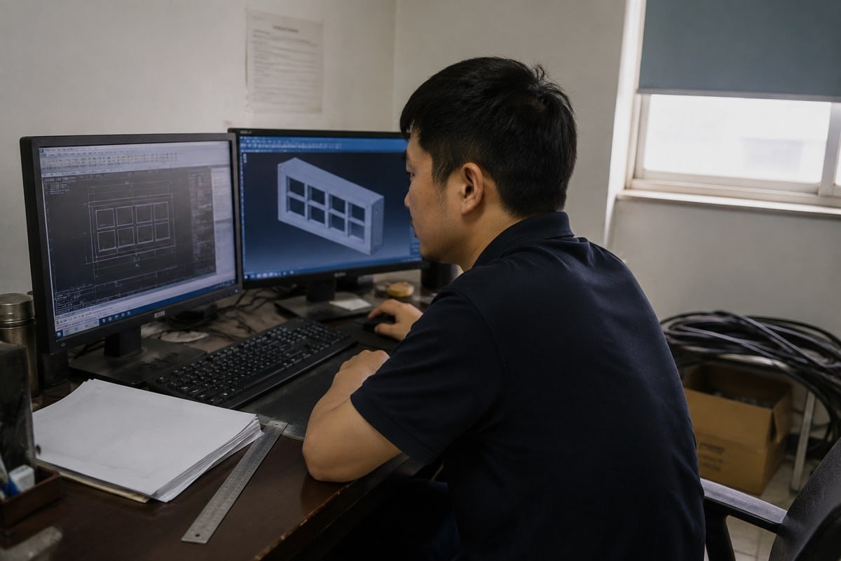
A good CAD drawing request names the format, the version, the units, and the intended use. Those four items prevent most re-sends. When a European integrator asks us for "the CAD," we ask back which of three jobs the file must do: cut the opening, model the assembly, or coordinate in BIM. Each job wants a different file.
Match the format to the job
| Format | Best use | What it carries | What it lacks |
|---|---|---|---|
| DWG / DXF | Cutting the opening on laser or water-jet; 2D drilling layout | Cutout dimensions, bolt hole centers, layer structure | No 3D body, tolerances only if annotated |
| STEP (AP214 / AP242) | 3D assembly of the cable sealing system in SolidWorks, Inventor, NX | Nominal geometry of frame, stay plates, compression unit, modules | Tolerances and torque notes are usually absent |
| PDF (dimensioned) | Controlled reference for approval and site use | Dimensions, notes, revision, signatures | Cannot be imported for machining |
| Revit family / IFC | BIM clash detection 5 in modular data centers and container plants | Parametric object with clearance zones | Fine hole detail is often simplified |
| Native (SLDPRT, IPT) | Only if your office runs the same package | Full feature tree | Version-locked, hard to share |
Ask for tolerances, not just geometry
A STEP file describes a nominal shape. It does not tell a fabricator how much the cutout may deviate before the frame no longer seats. If your shop cuts container walls with a laser, ask the supplier to state the recommended cutout tolerance and the hole diameter for the bolt size on the 2D sheet. We put this on our drilling diagrams by default, because a frame that lands 1 mm proud of the plate is a gasket problem, not a paint problem.
BIM objects versus static diagrams
For large marine, offshore, or modular data center programs, a static 2D diagram is no longer enough. Project teams want a smart object that carries the clearance envelope for cable bend radius on both sides. This lets clash detection flag a busbar or a tray before steel is cut. Suppliers increasingly support this design-before-build workflow through online configuration tools that output project-specific layouts. If your supplier cannot provide a BIM object, at minimum request the STEP model with the cable exclusion zone modeled as a transparent body.
Units, revision, and naming
State millimeters unless your drawing standard says otherwise. Ask for the revision block on every sheet and a file name that includes the project, opening ID, and revision. This sounds trivial. It is the difference between fabricating from revision B when revision C was approved.
How Can I Verify a Supplier's Drilling Diagram Matches My Existing 120-Frame Cutout?
On our QC bench we overlay every customer-supplied 120-frame template on the matching DEWIN frame before shipping. That habit started after a bolt pattern, not the modules, caused a mismatch.
Verify by comparing the supplier's diagram against your as-built cutout on four points: outer frame dimensions, internal packing space, bolt hole pitch and diameter, and flange thickness. Confirm the model cross-reference, then fit a free validation sample into the real opening before releasing fabrication.
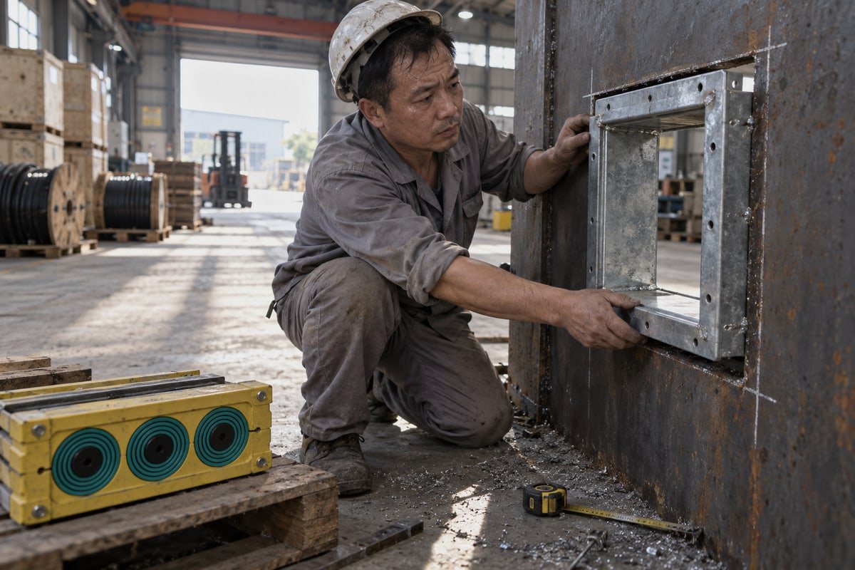
Second sourcing lives or dies on this step. Our TSC square modules and TSR round assemblies are built to drop into common 120-frame cutouts, and we publish model cross-reference tables from the incumbent model to the DEWIN equivalent. But a table is a claim. Your opening is a fact. The verification below turns the claim into evidence, and it is the same check we run before we say a frame is a qualified drop-in.
Step-by-step verification
- Measure the as-built cutout, not the old drawing. Openings drift during welding and painting. Record width, height, and corner radius at three points each.
- Pull the incumbent mounting frame specifications. Note the flange width, plate thickness, bolt size, and bolt pitch from the original installation drawing.
- Overlay the supplier diagram. Compare each dimension in the table below. Flag any difference larger than the supplier's stated installation tolerance.
- Check the packing space calculation. The internal window must hold your cable schedule plus spare modules plus stay plates. Count module rows, not just millimeters.
- Confirm the compression unit stroke. The compression unit needs a defined gap to reach rated pressure. If the frame is shallower than the original, check that the unit still closes fully.
- Fit the validation sample. Bolt a sample frame into a spare cutout or a test plate cut to your as-built dimensions. Insert the actual cables. Torque to the supplier's sequence.
- Sign off with documents. Attach the fit report, the A-60 or IP68 test documents, and the cross-reference line to your supplier qualification file.
What to measure and why
| Dimension | Where it fails | How to check |
|---|---|---|
| Outer frame width and height | Frame will not enter the cutout, or gap is too wide for gasket | Caliper at three points per side |
| Corner radius | Square frame binds in a radiused cutout | Radius gauge or template |
| Bolt hole pitch and diameter | Holes miss existing tapped holes or studs | Overlay printed 1:1 DXF on the wall |
| Flange thickness | Bolt length short; gasket under-compressed | Measure old flange, compare to drawing note |
| Internal window (packing space) | Modules do not fit, or spare capacity is lost | Stack modules dry, count rows |
| Stay plate positions | Rows misaligned with module heights | Compare row pitch to module nominal size |
| Compression unit depth | Unit cannot reach rated compression | Measure remaining gap after dry stack |
Why the sample matters more than the drawing
A drawing proves intent. A sample proves fit. Our step-core, halogen-free EPDM modules adapt across a range of cable diameters within one module size, which forgives small schedule changes. It does not forgive a bolt pattern that is off. That is why we send validation samples at no charge to sourcing teams qualifying a second source. One hour with a caliper and a torque wrench replaces weeks of email. Ask for the fit to be recorded on the drilling diagram as an as-built revision, so the next opening on the same project starts from verified numbers.
How Long Should I Expect to Wait for a Drilling Diagram and Validation Sample from My Supplier?
One lesson from a decade of exporting cable transit frames: the drawing itself is never the slow part. The questions before it and the courier after it are.
With a complete cable schedule, expect a project-specific drilling diagram within a few working days, and a revised drawing within one or two days per comment round. A validation sample usually follows in weeks rather than days, driven by stock availability, mold work for custom sizes, and international courier time.
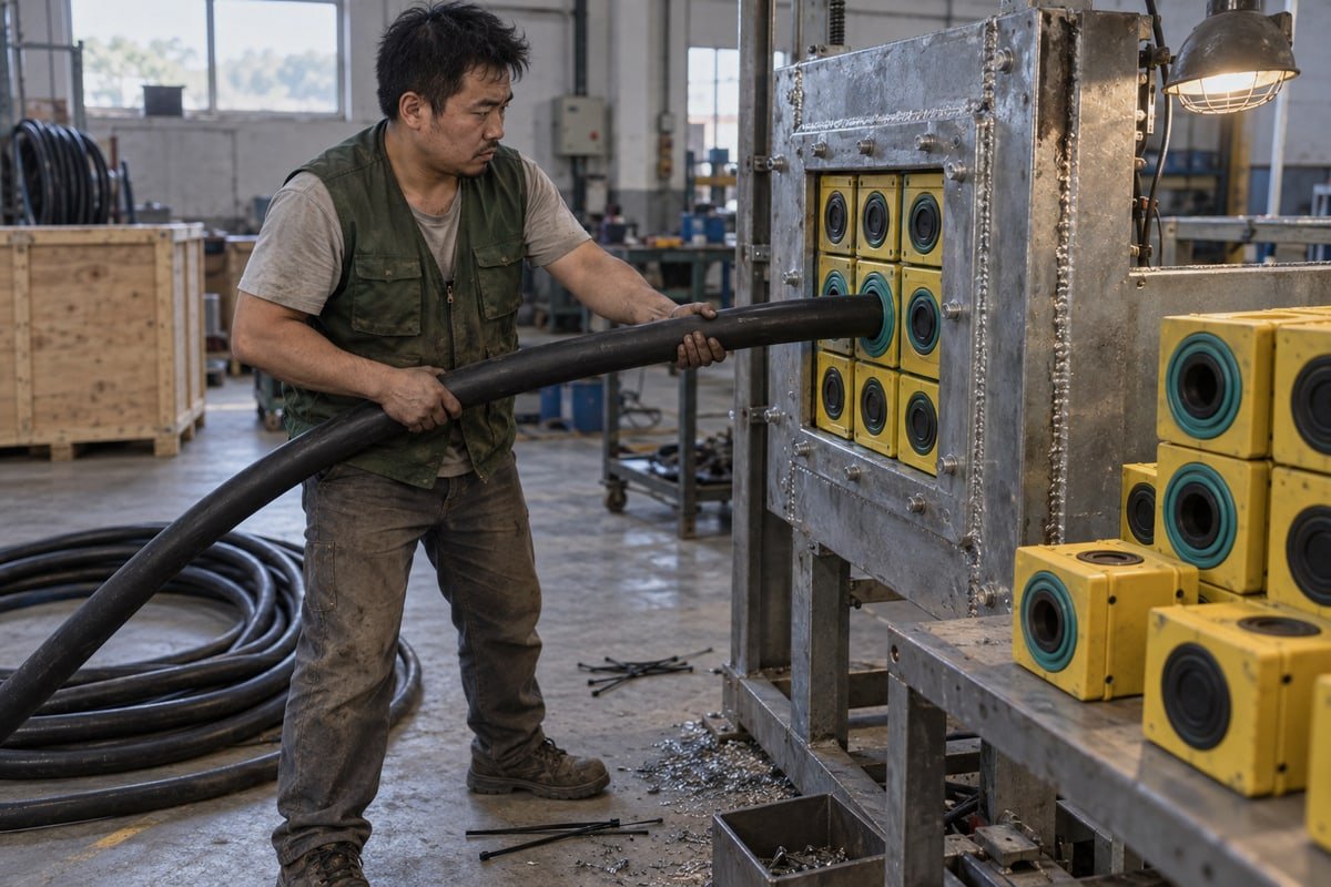
Lead time is a chain of small waits. When buyers ask us for a single number, I break it into stages instead, because each stage has a different cause and a different fix. The drawing stage is engineering time. The sample stage is factory and logistics time. Confusing the two produces unrealistic schedules.
The stages in order
| Stage | What happens | What controls duration |
|---|---|---|
| Data check | Supplier reviews the template, flags gaps | Completeness of your cable schedule |
| First drilling diagram | Engineer sizes aperture, selects modules, lays out bolt pattern | Standard 120-frame size vs custom frame |
| Buyer review | Your engineer compares against cutout and BIM model | Internal approval routing on your side |
| Revision rounds | Corrections to spare capacity, orientation, or deliverable format | Number of open questions per round |
| Sample release | Frame, modules, stay plates, and compression unit picked or made | Stock for standard sizes; in-house mold work for custom |
| Export and courier | Documents prepared, parcel shipped | Destination region, customs, chosen courier |
| Fit report | You bolt it in, torque it, and record results | Your site or lab availability |
What slows the drawing
Almost every long drawing cycle traces back to a missing field. The three most common gaps are no spare capacity percentage, no substrate thickness, and no statement of whether the opening is core-drilled, cast-in, or welded. Each one forces a question. Each question costs a day across time zones. We keep an English-speaking engineer on every inquiry so the reply lands the same working day, but the fastest reply is the one you never need.
What slows the sample
Standard frames and modules compatible with 120-frame cutouts ship from stock in normal conditions. Custom sizes need a mold. Because our mold shop is in-house, that step stays under our control rather than a subcontractor's, but it still adds time. Export documentation is prepared in parallel, not after. Courier time to Europe, Asia-Pacific, or the Middle East is the last variable, and it is the one neither party can compress much.
How to compress the whole cycle
- Send the cable schedule and template together with the RFQ, not after quotation.
- Name the deliverables up front: drilling diagram, installation drawing, DWG, STEP, or all four.
- Approve the drawing for sample release before the final BIM sign-off, if the frame envelope is already fixed.
- Ask the supplier to ship the sample with the A-0/A-60, IP68, and pressure test documents in the same parcel.
- Book your test plate or spare cutout before the parcel arrives.
Follow those five steps, and the whole cycle from request to fit report runs in parallel tracks instead of in series.
Conclusion
Late, incomplete requests stall fabrication. Send the full cable schedule, name your file formats, verify against the real cutout, and fit a validation sample first.
Footnotes
1. ISO 19026:2015 is the international standard for ships and marine technology regarding multi-cable transits. ↩︎
2. ISO 10303-242 is the international standard for managed model-based 3D engineering data exchange. ↩︎
3. General engineering concept of reserving space or resources for future expansion or design changes. ↩︎
4. IMO safety standards govern fire protection and seal integrity requirements in maritime and offshore environments. ↩︎
5. Overview of BIM-based clash detection processes used in construction and modular engineering. ↩︎



 English
  Español de México
  Deutsch
  Français
  العربية
  Русский