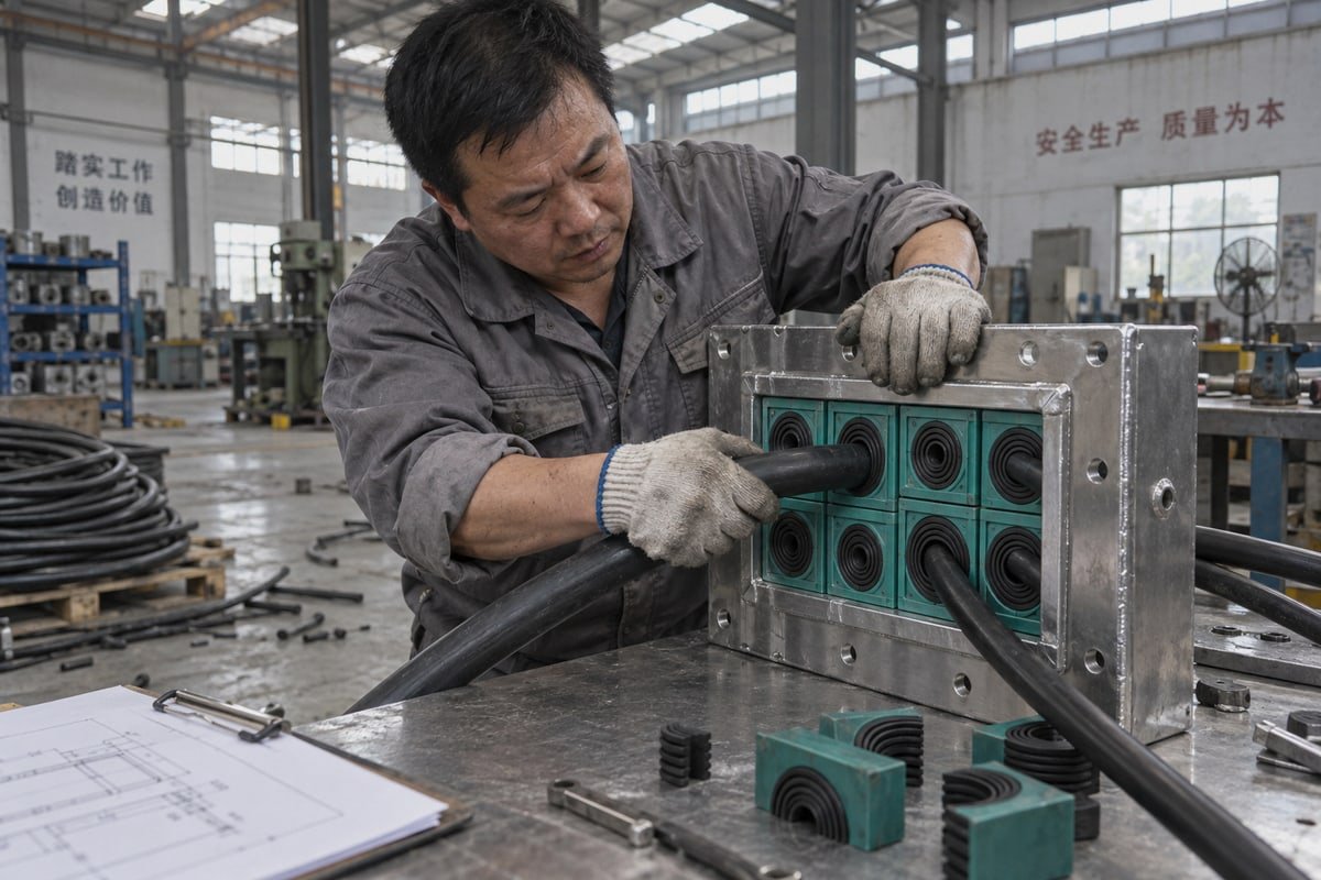
Physical mock-up vs drawing review is a question our engineers face on every e-house cable transit order leaving our Shaanxi plant. Get it wrong, and [rework](https://dewinmct.com/?p=701) eats the schedule.
A physical mock-up prevents more rework than drawing review alone for e-house cable transit suppliers, because it exposes fit, bend radius, tightening access, and sealing problems that drawings hide. Drawing review is the cheaper first filter; the mock-up or first-article check is the final risk control.
Neither method replaces the other. Below, I break down which risks each one catches, what evidence to demand from a second-source supplier, and how to sequence both so the frame fits first time.
How do I decide between a physical mock-up and a drawing review when qualifying a cable transit supplier for my E-House?
The trade-off we weigh with every new OEM account is simple: a drawing review costs days, a mock-up costs weeks, and site rework costs far more than both.
Decide by complexity and rework cost. Use drawing review alone for repeat standard modules with proven transit families. Add a physical mock-up for first-time designs, dense cable packing, strict segregation, IP68 or A-60 requirements, or remote sites where re-entry is expensive. Most e-house programs need both, in sequence.

Rework in an e-house context has a specific shape. It means a transit frame that lands on a stiffener, a module bore that will not close around a stiff 4-core power cable, a compression bolt no wrench can reach, or a seal that fails the water test after the panel is closed. Each of these triggers engineering change orders, re-entry labor, and a delay to Factory Acceptance Testing. The question is which validation step catches which failure.
What each method actually catches
| Risk in e-house cable transit work | Drawing review | Physical mock-up |
|---|---|---|
| Frame-to-structural-steel clash | Yes, through clash detection in 3D BIM coordination 1 | Yes, but late |
| Code spacing and segregation (NEC, power/control separation) | Yes | Partly |
| Bend radius and "memory" of large-diameter cables | No | Yes |
| Hand-room for torque wrench and compression tools | Rarely | Yes |
| Tolerance stack-up in fabricated steel cutouts | No | Yes |
| IP68 and gas-tight sealing 2 under real compression | Paper only | Yes |
| Thermal behavior of dense bundles inside the transit | Estimate only | Yes, with the real bundle |
| What-if planning for future cable additions | Yes, fast and cheap | Slow |
The pattern is clear. Drawing review is strongest on spatial constraints 3, interfaces, and compliance. The mock-up is strongest on anything that depends on how rubber, steel, and cable actually behave together.
A simple decision rule
- Run drawing review on every project. It is the cheapest way to remove obvious errors and to freeze the cutout dimensions and cable schedule.
- Skip the mock-up only when the transit family is proven, the cable mix is ordinary, and the module is a repeat standard part.
- Build a mock-up when any one of these is true: first-time design, dense cable packing, complex segregation rules, IP68 or A-60 firestop compliance in the acceptance language, or offshore and remote-site installation.
Two objections I hear from procurement
Buyers often push back on mock-up cost. My answer is that a mock-up does not have to be a full e-house. One frame, one gland plate section, and the real cable mix is enough to prove installability. The second objection comes from suppliers themselves: a mock-up can validate the wrong baseline if the OEM's upstream design is still moving. That is a fair point. It is exactly why drawing review comes first. Lock intent on paper, then prove it in physical form. In modular substation construction, where several parties own different parts of the design, that sequence keeps everyone testing the same thing.
What validation evidence should I request before approving a drop-in replacement for our existing 120-frame cutouts?
A sourcing engineer in Europe once sent us a single frame drawing and asked whether our TSC modules would fit. We asked for the cutout tolerances first.
Request a model cross-reference table mapping your existing module codes to the replacement, dimensional drawings with cutout tolerances for the 120-frame, free validation samples for a fit check, and test documents covering IP68, A-0/A-60 fire rating, and gas-tight sealing from 0.01 to 0.4 MPa.
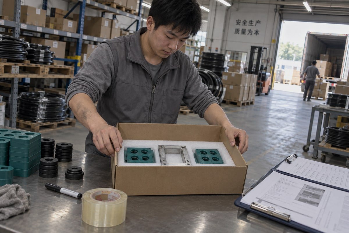
A drop-in replacement lives or dies on evidence, not on a claim of compatibility. When we qualify our TSR and TSC series as a second source into an existing 120-frame, we expect the buyer to be skeptical. That is healthy. Here is the evidence package I would ask any cable transit supplier to produce, and what each item actually protects you against.
The six-item evidence package
- Model cross-reference table. It maps each incumbent module code to the replacement code, with bore range and outer dimension side by side. This is your interchangeability proof.
- Dimensional drawings with tolerances. Nominal 120 mm frame height is not enough. You need the module outer dimension tolerance and the frame inner dimension tolerance, so you can judge the stack-up.
- Free validation samples. Two or three cable sealing modules in the sizes that matter, compressed in your own frame with your own cable. This is the smallest possible physical mock-up.
- Test reports. IP68 ingress protection, A-0/A-60 fire rating 4, and watertight and gas-tight sealing across 0.01–0.4 MPa. Ask for the actual documents, not a summary line on a datasheet.
- Quality system certificates. ISO 9001 and IATF 16949 show the process is controlled. A BV-approved factory status shows a third party has looked at it.
- Material declaration. For our modules, that means step-core, halogen-free EPDM. Halogen-free matters for smoke toxicity in enclosed e-houses.
Which evidence prevents which rework
| Evidence | Question it answers | Rework it prevents |
|---|---|---|
| Cross-reference table | Does module X replace module Y? | Wrong module ordered against existing BOM |
| Toleranced drawings | Will the stack-up close? | Modules too tight or too loose in the frame |
| Free validation samples | Does it install with our cables and tools? | Bend radius, hand-room, compression failures |
| IP68 and gas-tight test reports | Will the seal hold at pressure? | Water-ingress failures after panel close-out |
| A-0/A-60 fire reports | Does it meet firestop compliance? | Rejected acceptance inspection |
| ISO 9001 / IATF 16949 / BV | Will batch two match batch one? | Field variation across a multi-unit program |
Why tolerance stack-up deserves its own line
E-house steel is fabricated, not machined. Weld distortion and cutting tolerance accumulate. A module that is dimensionally correct on paper can still bind when the frame inner width is at the low end of its range. Our answer is to state module tolerances on the drawing and to send samples so the buyer checks the fit in their own frame, not ours. If the acceptance language for Factory Acceptance Testing includes a water-ingress check, ask the supplier to show the same test on the same module size before approval.
Can free validation samples reduce rework risk more effectively than relying on CAD drawings alone?
On our Shandong line, every sample module is compressed against a reference cable set before it ships. The rubber sometimes behaves differently than the STEP file suggests.
Yes. Free validation samples reduce rework risk more effectively than CAD alone because they let you test real cable stiffness, step-core compression, and hand-room in your own frame before committing a purchase order. CAD confirms dimensions; the sample confirms installability. Use both, but never approve on CAD only.
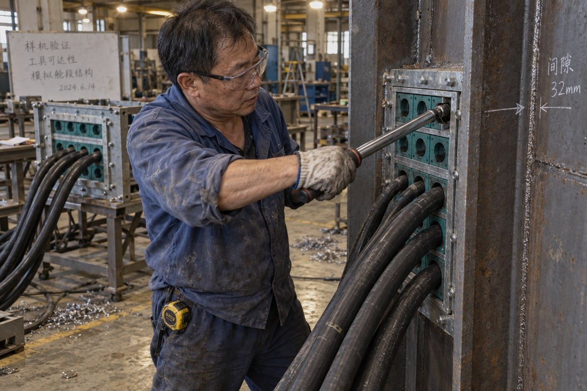
CAD is honest about geometry and silent about behavior. A STEP file of a multi-cable transit system 5 shows a perfect cylinder passing through a perfect bore. The real cable is a stiff, armored conductor with memory from the drum. The real bore is EPDM that compresses and grips. The gap between these two pictures is where most on-site rework hides. A free sample closes that gap at almost no cost to the buyer.
What a sample reveals that a STEP file cannot
- The bend radius reality gap. Large-diameter power cables resist seating. In CAD they follow any path. In the frame they push modules out of line and fight the stay plate. Only a physical check shows whether the cable will sit where the drawing says.
- Ergonomic constraints. A compression unit needs a wrench on it. 3D CAD rarely models the hand, the tool swing, or the adjacent cable tray. A sample in the frame shows immediately whether the bolt can be torqued.
- Step-core compression behavior. Our step-core design lets one module size cover a range of cable diameters. The sample lets the installer peel to the right step and feel the compression, which is a workmanship check no drawing can offer.
- Thermal behavior. With the real bundle in place, you can run a short heat-soak and see whether dense packing creates a heat trap. This is early-stage design validation for insulation life, not just fit.
Turning a sample into a mini mock-up
- Freeze the cutout dimension and cable schedule from the drawing review. Do not sample against a moving target.
- Fit the samples into one real frame, ideally a cutout from the actual e-house fabrication batch.
- Route the real cables, including the largest and stiffest.
- Compress with the production torque and the production tool.
- Check hand-room, alignment, and seal contact. Photograph everything.
- Use the assembled frame as the First-of-Kind benchmark for training the installation crew.
Where samples fall short
A few samples cannot prove a full-frame water-ingress test or an A-60 fire rating. That is what the test reports are for. And if your upstream design is unstable, a sample validates the wrong baseline. This is the supplier caution view, and it is correct. The fix is sequencing, not skipping the sample. Paper first, then rubber.
Which supplier documentation—test reports, cross-reference tables, or STEP files—best predicts fit-first-time success on-site?
One lesson from more than a decade of exporting compression units: no single document predicts fit. Each file answers a different question, and the gaps between them cause the rework.
STEP files best predict geometric fit, cross-reference tables best predict interchangeability with your existing 120-frame modules, and test reports best predict sealing and fire performance. For fit-first-time success, STEP files rank first, but only when paired with a cross-reference table and a physical sample check.

Engineering-minded buyers in Europe tend to ask for all three documents at once, and then weight them equally. In my experience they should not be weighted equally. They should be ranked by the question you are trying to answer at each stage of qualification.
Ranking by predictive value for fit
- STEP files. Native 3D geometry drops straight into your 3D BIM coordination model. Clash detection runs against the real frame envelope, bolt positions, and module stack. This is the strongest predictor of geometric fit, provided the model carries tolerances and not just nominal dimensions.
- Cross-reference tables. These predict whether the new part slots into your existing BOM, spares list, and installation instructions without changing procedures. They prevent the quiet rework of a crew installing a module that looks right but has a different bore range.
- Test reports. IP68, A-0/A-60, and gas-tight results from 0.01 to 0.4 MPa predict whether the installed seal will pass acceptance. They do not predict fit, but a fit-first-time frame that fails the water test is still rework.
Side-by-side comparison
| Document | Best at predicting | Blind spot | How we handle it |
|---|---|---|---|
| STEP file | Geometry, spatial constraints, clashes | Cable stiffness, hand-room, rubber behavior | Supplied with tolerances; paired with free samples |
| Cross-reference table | Interchangeability, BOM continuity | Physical stack-up in a fabricated frame | Existing model → DEWIN model, with bore ranges listed |
| Test report | Sealing, fire, gas-tight performance | Nothing about dimensions | ISO 9001 / IATF 16949 controlled, BV-approved, issued on request |
The hybrid step most teams skip
There is a low-cost bridge between paper and mock-up. Projecting the digital transit layout onto the physical e-house frame with augmented reality, or even a full-scale printed template, catches structural interferences before apertures are permanently cut. It is not a substitute for a compressed sample with real cables. But it costs almost nothing and it protects the one operation you cannot undo, which is cutting the steel.
The sequence that predicts success
Drawing review with STEP files and cross-reference tables locks intent and interchangeability. Free validation samples in a real frame prove installability. Test reports back the acceptance criteria. Then a controlled production release. When we work this way with OEM integrators, the on-site question changes from "will it fit?" to "did the crew follow the benchmark?" That is a much cheaper question to answer.
Fazit
Rework on an e-house transit is expensive and avoidable. Review on paper to lock intent, prove with samples to confirm fit, and back it with test documents.
Fußnoten
1. Official authority for open BIM standards used in coordination and clash detection for modular construction. ↩︎
2. The IEC provides international standards for electrical equipment sealing and environmental protection. ↩︎
3. Conceptual definition of spatial constraints relevant to 3D modeling and engineering design reviews. ↩︎
4. The International Maritime Organization sets global standards for fire resistance in marine and offshore structures. ↩︎
5. Technical overview of cable transit systems used to maintain the integrity of walls and floors. ↩︎



 English
  Español de México
  Deutsch
  Français
  العربية
  Русский