
A revised drawing reached our factory last month with the old cable diameters still attached IATF 16949 1. Recalculating sealing dimensions after drawing updates is where multi cable transit projects quietly fail.
To recalculate sealing dimensions after drawing updates for multi cable transit systems, re-measure the revised frame opening, rebuild the cable schedule by actual outside diameter, reselect modules and fillers against the manufacturer’s packing space rules, re-check spare capacity and clearance, then revalidate the full stack-up before ordering.
That sounds simple. In practice, each of those steps has a trap. Below I walk through the four questions our purchasing contacts ask most often, and I show the checks we run on our own production line before a transit ships.
How can I quickly verify if a drawing revision still matches my existing MCT frame cutout?
During incoming inspection at our Shaanxi plant, we once caught a frame drawing where the cutout had grown by a few millimetres while the transit schedule stayed untouched.
Overlay the revised drawing on the approved one and compare cutout width, height, wall thickness, and installation depth against the frame's external and internal dimensions. If any value changed, or the cable list changed, the old cutout match is void and a fresh sizing check is required.
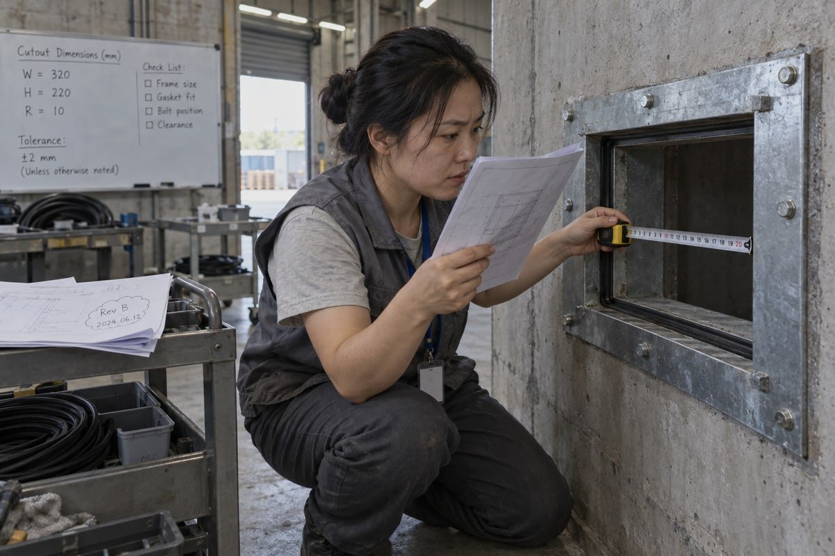
The mistake I see most often is treating a drawing revision as a paperwork event. It is not. It is a geometry event, and geometry drives the seal.
What counts as a drawing update in practice
A drawing update is any change that affects the frame, the cables, or the space around them. That includes a changed opening size, a different wall thickness, a shifted cable centerline, a new cable added, an old cable removed, a revised tolerance, or an equipment layout shift that eats into installation depth. Each of these can change the required module stack, the filler arrangement, and the final compression fit. So I tell buyers: if the revision cloud touches the penetration area, assume the transit needs a fresh check.
A fast revision checklist
Our engineers use a short comparison table before they touch any module selection. It takes ten minutes and it catches most problems.
| Item to compare | Why it matters | Rule we apply |
|---|---|---|
| Cutout width and height | Frame external size must fit; frame internal dimensions set the packing space | Cutout must match frame plus welding or bolting allowance |
| Wall or bulkhead thickness | Affects frame depth and compression unit reach | Confirm frame depth still spans the wall |
| Free space at front and back | Needed to compress the seal properly | Keep roughly 15–20 mm clear on both faces |
| Free space inside the frame | Needed for stayplate positioning and wedge travel | Leave at least 15 mm free at both sides inside the frame |
| Cable centerlines and routes | Changes the bundle shape entering the frame | Re-map every cable to a row |
| Cable count and cable diameter tolerances | Drives insert block sizing | Rebuild the cable schedule from measured values |
If every row in that table reads "unchanged", you can keep the existing cutout. If even one row changed, move to a full recalculation. Do not patch only the affected cable. A single larger cable can push a row wider, which shifts the stay plate, which changes the row below it.
One more point on as-built documentation. The approved drawing is only useful if it reflects what was actually installed. Before comparing, confirm that the "approved" version matches the field frame. We have seen cases where the site installed a different frame size than the drawing showed, and the revision comparison was against the wrong baseline from the start.
What tools or model cross-reference tables help me recalculate sealing module dimensions after a drawing change?
Every week our engineers weigh the same trade-off: a manual table gives full control over the packing space calculation, while vendor software is faster but hides its assumptions.
Use the manufacturer's module size table, a cable schedule sorted by measured outside diameter, and a model cross-reference table mapping existing modules to compatible 120-frame equivalents. Software such as Roxtec Transit Designer or RGPlan automates fill ratio and module selection; a spreadsheet remains the audit trail.

Buyers often ask which method is "right". My honest answer is that both work, but they fail in different ways. Here is how I compare them.
| Method | Strength | Weakness | Best used when |
|---|---|---|---|
| Manual tables and spreadsheet | Full visibility of every assumption; easy to audit | Arithmetic errors; slow on large schedules | Small revisions, qualification reviews, second-source checks |
| Vendor sizing software | Fast; automatic fill ratio and filler calculation | Locked to one vendor's module family; assumptions hidden | Large schedules, repeat projects, early design |
| Cross-reference table plus samples | Lets you swap module brands without redrawing the frame | Still requires a diameter check per module | Drop-in second sourcing on an existing 120 frame |
How standardized module families make recalculation manageable
Most modular sealing system 2 suppliers, including us, build around a standardized grid. Common packing spaces are 120×60 mm, 120×120 mm, 120×180 mm, and 120×240 mm. One published white paper notes that six module sizes can cover cable outside diameters from 3 mm to 99 mm. Our TSC square modules and TSR round assemblies follow the same 120-frame logic, and the step-core EPDM adapts to a band of diameters within one module size. That is why a drawing change rarely forces a new frame. It usually forces a new module mix inside the same frame.
What our cross-reference table gives you, and what it does not
| Input you have | What the cross-reference table returns | What you must still verify |
|---|---|---|
| Existing module part number | Equivalent DEWIN TSC or TSR model with matching footprint | Measured cable diameter falls inside the step-core range |
| Existing frame size | Compatible 120-frame packing space | Free space of at least 15 mm inside the frame on both sides |
| Existing compression unit | Matching DEWIN compression unit height | Compression wedge adjustment travel after the new stack-up |
The recalculation sequence we follow
- Mark every dimensional change between the approved and revised drawings.
- Rebuild the cable schedule with measured outside diameters, not nominal conductor sizes.
- Sort cables by diameter and place the largest, heaviest cables in the bottom row so smaller modules are not crushed.
- Calculate the cable fill ratio using module footprints, not raw cable area. Visual fill is misleading; the space between blocks reduces the usable area.
- Insert a stay plate between every row so modules do not shift during compression and the fire-rated penetration seal stays intact.
- Check compression wedge travel and front/back clearance, then document the stack-up.
A note on other systems: in a Brattberg-type insert block design, the block depth is 60 mm and two insert blocks are used per cable. The counting rules differ from a step-core module system. So never copy a block count from one family into another. Recalculate from the diameter list every time.
Can I request free validation samples to confirm new sealing dimensions before committing to a full order?
A sourcing engineer in Germany emailed us after a BESS container drawing revision. He did not want a quote first; he wanted two sample modules and the test reports.
Yes. We supply free validation samples of sealing modules and matching spare parts so you can test-fit the revised cable schedule in your existing 120-frame cutout before a full order. Send the updated drawing and measured cable diameters; we match the sample set to it.
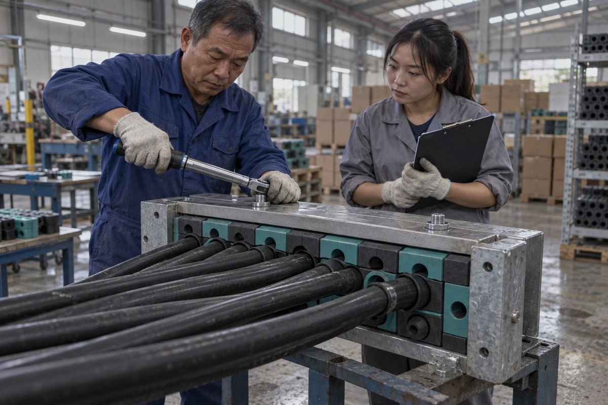
I understand the skepticism behind that request. A datasheet says a module covers a diameter band. A drawing says the frame is a certain size. Neither document proves the two work together on your actual cable. Only a test fit does.
Why revalidation beats partial reuse
Some teams prefer to adjust only the cables that changed and keep the rest of the transit untouched. I hear the argument: less work, less cost. But a multi cable transit is one compressed assembly, not a set of independent seals. Change one row and the compression load on every other row changes too. That is why our position is to revalidate the whole stack-up whenever the drawing changes materially, and free validation samples are the low-cost way to do it.
What to test on the sample set
| Check | How to do it | What a pass looks like |
|---|---|---|
| Diameter fit | Peel the step-core to the measured cable diameter and insert the cable | Even contact around the jacket with no gap and no over-peel |
| Footprint fit | Place the sample beside the existing modules in the frame | Same height and width as the incumbent 120-grid module |
| Compression response | Tighten the compression unit to the specified travel | Modules stay square; stay plates remain straight |
| Compression set on reused modules | Release compression on old modules and measure recovery | Old modules that stay flattened have lost elastic memory and should be replaced |
| Jacket material behaviour | Note whether cables are XLPE, PVC, or silicone | Confirm the elastomer grip holds across your service temperature range |
That last row matters more than people expect. Silicone and XLPE jackets expand differently with temperature. In a BESS container or an outdoor switchgear cabinet, the seal must hold at both ends of the range. The sample lets you check this on your own cable instead of trusting a generic claim.
What comes with the sample
Our target buyers read test documents before they reply to an email, so we send the evidence with the parts. That includes our ISO 9001 3 and IATF 16949 system certificates, the BV factory approval, and the test documents for fire rating A-0/A-60 4, IP68 ingress protection 5, and watertight and gas-tight performance from 0.01 to 0.4 MPa. If your revised drawing calls for a specific pressure or fire class, tell us which report you need and we attach it.
Spare capacity planning also belongs in the sample stage. If your revised schedule uses nearly all of the packing space, ask for spare modules in the sample set. Keeping 20% to 30% free capacity in the frame means the next drawing revision adds a module instead of replacing the housing. That is the cheapest insurance in the whole assembly.
How do I get updated CAD or STEP files to align my design after a Multi Cable Transit drawing revision?
One lesson from years of exporting to EPC contractors: a PDF datasheet never stops a collision in a 3D model, but a native STEP file does.
Request STEP, IGES, or 2D DXF files directly from the manufacturer's technical support with the revision number, frame model, and cable schedule attached. Reputable suppliers issue files per module and frame size within days, so you can rebuild the assembly and run collision checks before release.
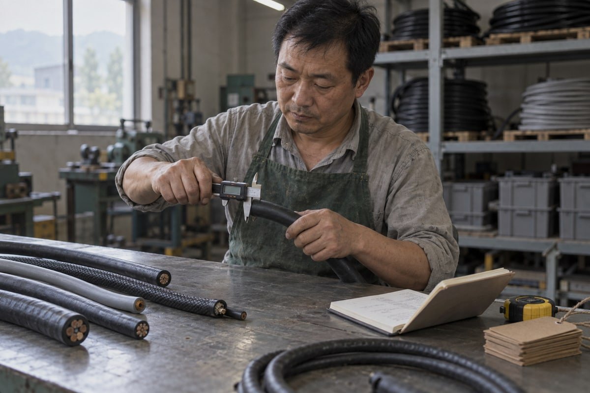
CAD files are only useful if they match the parts you will actually receive. So the request has to carry the same information as the order. Here is what our English technical support team asks for, and why.
What to include in the file request
- The drawing revision number and date, so the files are tied to the right baseline.
- The frame model and frame internal dimensions, including wall thickness.
- The revised cable schedule with measured outside diameters and cable types.
- The module list you have already selected, or a request for us to propose one.
- The file format your CAD system needs, usually STEP for 3D and DXF for 2D.
- Any custom size, because our in-house mold shop can produce non-standard modules and those need their own files.
Rebuilding the assembly after the files arrive
Once the files land, rebuild the transit as an assembly, not as a single block. Place the frame, then the bottom stay plate, then each row of modules, then the compression unit. This exposes problems that a solid block hides: a compression wedge that cannot travel because a cable tray sits too close, or a row that clashes with the enclosure door. Run collision detection against the surrounding equipment. If your project keeps a digital twin, load the transit assembly into it so later layout changes trigger a sealing check automatically.
Keeping the physical frame and the digital model in sync
The last step is cable schedule management after installation. We recommend a simple field practice: fix a label or QR code on each frame's nameplate that links to the current as-built stack-up drawing. A technician can scan it, compare the installed modules to the latest revision, and flag any difference before it becomes a leak or a fire-rating failure. It also makes ordering spare sealing modules straightforward, because the part list is already attached to the frame.
| Document | Owner | Update trigger |
|---|---|---|
| Approved drawing with revision number | Design engineer | Any change to cutout, cables, or layout |
| Module stack-up sheet | Transit designer | Any change to the cable schedule |
| STEP and DXF files | Supplier technical support | New revision or new module selection |
| As-built documentation and frame label | Installer or commissioning team | After installation and after every modification |
Conclusion
Drawing updates quietly break old transit schedules. Re-measure, rebuild the cable list, reselect modules, revalidate with samples and STEP files, then document the as-built state every time.
Footnotes
1. Official oversight site for the automotive quality standard required for industrial manufacturing components. ↩︎
2. Wikipedia entry explaining the fundamental technology and application of modular cable transit systems. ↩︎
3. Official ISO page for the quality management standard mentioned in the article’s compliance section. ↩︎
4. International Maritime Organization page detailing fire protection standards for A-class divisions. ↩︎
5. International standard for ingress protection ratings, specifically explaining the IP68 level mentioned. ↩︎



 English
  Español de México
  Deutsch
  Français
  العربية
  Русский