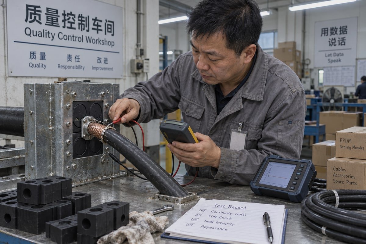
[Cable shield bonding at wall penetrations](https://dewinmct.com/?p=378) fails quietly. On our transit frame test bench, a sealed, watertight wall still leaked noise because the braid never touched metal. That is fixable.
Cable shield bonding at wall penetrations meets EMC requirements when the screen makes a 360-degree, low-inductance, metal-to-metal contact at the point of entry. Verify it by visual inspection, four-wire bonding resistance measurement, transfer impedance or TDR checks, and the supplier’s shielding effectiveness test reports.
Continuity alone does not prove compliance. The bond must be full-perimeter, low-impedance, and located exactly where the cable crosses the wall. Below I walk through the standards, the bench tests, the documents, and the sample process that let you prove it before a bulk order.
What EMC standards should I reference when specifying shield bonding at cable transit walls?
Last year a QC engineer on our Shandong line asked which EMC standard governed a data center transit frame. The drawing said only: bond shield. That was not enough.
Reference IEC 61000-5-2 for shield bonding and earthing practice, IEEE 299 or IEC 61587-3 for enclosure shielding effectiveness, IEC 62153-4-3 for transfer impedance, plus the product standard your equipment must pass, such as EN 55032, IEC 61800-3, IEC 60533 or MIL-STD-461, which sets the pass thresholds.

A cable transit wall is not one thing. It is a boundary between two EM zones. The standards you cite must cover three separate questions: how the shield is bonded, how the wall performs as a shield, and what limit the finished system must meet. Most specifications I receive from Europe only cover the third question. That leaves the installer guessing about the first two, and the guess is usually a pigtail.
Why wall penetrations are the weak point
A steel container wall is a good Faraday cage 1 until you cut a hole in it. Every aperture, seam, and cable entry lowers shielding effectiveness. A gap around a cable becomes a slot antenna once its length approaches half a wavelength of the noise. At data center and BESS switching frequencies, that is a gap of a few centimeters. So Faraday cage integrity depends on the transit, not on the wall plate.
Which standard answers which question
| Question | Standard to cite | What it gives you |
|---|---|---|
| How should the shield be bonded at entry? | IEC 61000-5-2 | Installation practice: 360-degree termination, no pigtails, bond at zone boundary |
| Does the transit keep the wall shielded? | IEEE 299, IEC 61587-3 | Shielding effectiveness test method for enclosures and cabinets |
| How good is the bond itself? | IEC 62153-4-3 | Transfer impedance test for the screen and its termination |
| What limit must the system pass? | EN 55032 / EN 55035, IEC 61800-3, IEC 60533, MIL-STD-461 | Emission and immunity limits for IT, drives, marine, and military equipment |
| What about lightning surge? | IEC 62305 | Bonding at the building or container boundary for surge current |
Single-point or both-ends? A real buyer objection
Purchasing engineers often push back here. Their analog instrument vendor says bond the shield at one end only, to avoid ground loops. Their PLC vendor says bond at both ends. Both are right for their own frequency range. Below a few kilohertz, one-end bonding can protect a low-level analog loop. Above that, inductance dominates and the shield only works when bonded at both ends and at the wall. My advice is simple. Bond every screen to the transit at the wall for high-frequency protection. Then apply the one-end rule to the inner analog drain if the system concept requires it. The transit bond and the signal reference bond are two different decisions.
How do I test 360-degree shield continuity through an MCT sealing module before installation?
Compression torque on a transit frame pulls two ways for us: enough to hold IP68, yet not so much that the braid contact inside an EMC module shifts.
Assemble the module, exposed braid and frame on a bench fixture, then measure bond resistance with a four-wire milliohm meter at four points around the circumference, targeting 2.5 milliohms or less, and confirm with a TDR sweep that no inductive bump appears at the interface.
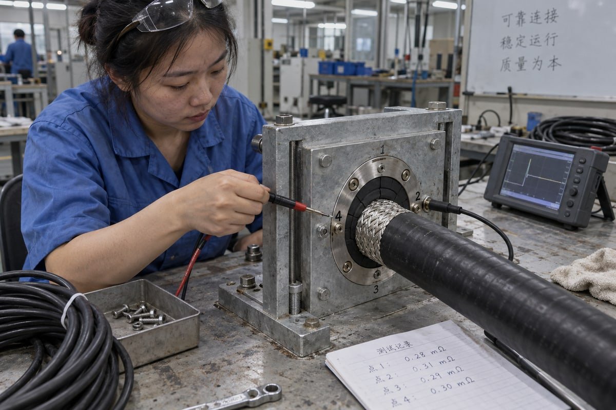
A standard sealing module is an insulator. Our halogen-free EPDM 2 step-core blocks are chosen for fire rating and gas-tight sealing, not conductivity. An EMC transit adds a conductive contact element inside the module so the exposed braid presses against metal, and that metal presses against the frame. Your bench test must prove that whole chain, not just the braid.
A bench workflow that works
- Strip the cable jacket to the length shown on the module drawing. Do not trim the braid back past the contact zone.
- Remove paint, powder coat, or anodizing from the frame contact face. Check surface conductivity with a simple two-point ohm check before anything else.
- Fit the module, insert the stay plates, and torque the compression unit to the value on the nameplate.
- Run a bonding resistance measurement with a four-wire milliohm meter from braid to frame, at four positions 90 degrees apart.
- Sweep the joint with a TDR. Look for an impedance step at the wall interface.
- Sniff the circumference with an H-field near-field probe while a signal generator drives current on the braid.
What each test proves
| Test | What it proves | Practical threshold | What it misses |
|---|---|---|---|
| Visual inspection | Braid contacts metal all around | No visible gap, no paint, no coiled drain wire | High-inductance geometry that looks fine |
| Four-wire DC bond resistance | Low-resistance metal-to-metal contact | 2.5 milliohms or less braid to bulkhead | Inductance; a pigtail can also read low |
| Shield loop resistance | End-to-end screen path is intact | 0.6 ohm maximum cited for data cables | Location of the weak spot |
| TDR sweep | No inductive discontinuity at the wall | No impedance bump at the transit position | Absolute shielding level |
| Transfer impedance | Ratio of inner voltage to outer current | Compare against the cable's own transfer impedance curve | Requires a proper test fixture |
| Near-field H-probe scan | Localized leakage from uneven clamping | Uniform reading around the circumference | Needs a repeatable probe distance |
Failure modes we catch most often
Uneven readings around the circumference usually mean uneven compression. One side of the module reads 2 milliohms and the other side reads 40. That is a clamping pressure problem, not a material problem. The other common finding is galvanic corrosion risk. A tinned copper braid against a bare aluminum plate will pass on day one and drift on day three hundred. Ask for the plating spec of the contact element and check it against the braid material before you sign off. The remaining classics are a long drain wire, a shield trimmed too far back, and incidental contact with an unbonded metal bracket inside the frame.
Which certification documents should I request to confirm EMC compliance for drop-in transit frames?
A sourcing manager in Germany once sent me a one-line request: prove EMC compliance. I sent nine documents back, and we then discussed which three actually mattered.
Request a shielding effectiveness test report per IEEE 299 or IEC 61587-3 for the exact frame and module combination, a transfer impedance or bond resistance report, plating and surface conductivity specifications, material declarations, the type approval certificate, and a cross-reference sheet proving dimensional compatibility.

The mistake I see most often is treating a certificate as proof of everything. Our factory holds ISO 9001 3 and IATF 16949 systems and is BV-approved. Our modules carry A-0 and A-60 fire ratings, IP68 ingress protection, and watertight and gas-tight test results from 0.01 to 0.4 MPa. None of those documents proves an EMC bond. They prove the seal, the fire barrier, and the process discipline behind them. EMC needs its own evidence, and that evidence must name the exact parts you will install.
The document set and what each one proves
| Document | What it actually proves | Red flag to watch for |
|---|---|---|
| Shielding effectiveness test report (IEEE 299 / IEC 61587-3) | The frame plus module keeps the wall shielded across a stated frequency range | Report covers a different frame size or a different module type |
| Transfer impedance or bond resistance report | The braid-to-frame contact is low-impedance | Only a DC continuity value, no frequency data |
| Plating and surface conductivity specification | Contact faces stay conductive and resist galvanic corrosion | Painted or powder-coated contact zone with no bare metal called out |
| Material declaration (halogen-free EPDM, conductive element) | Fire, smoke, and compatibility with your cable jackets | Missing halogen-free statement for data center or marine use |
| Type approval and fire test certificate (A-0 / A-60) | Fire and sealing performance of the same module family | Certificate number does not match the drawing |
| IP68 and pressure test documents | Ingress protection and gas-tight sealing | Test pressure lower than your site requirement |
| Cross-reference table and CAD/STEP files | The frame drops into an existing 120-frame cutout | Dimensions given as nominal only, no tolerance |
| ISO 9001 / IATF 16949 4 certificates | The factory controls the process batch to batch | Certificate issued to a trading company, not the plant |
Match the report to the part number
A shielding effectiveness figure 5 is only meaningful for the tested assembly. If the report covers a frame with conductive gaskets between frame and wall, and your installation uses a painted wall without gaskets, the figure does not transfer. Ask three questions. Which frame size was tested? Which module variant and contact element? How was the frame bonded to the test enclosure wall? If any answer is missing, ask for a retest on your configuration or plan your own system-level EMC test.
Why we keep drawings and evidence up front
Engineering buyers in Europe read spec sheets before they reply. So we send the cross-reference table first, mapping the existing model to the DEWIN model, then the test documents on request, then the STEP files. With 38 granted patents on our own designs, we have no reason to hide behind vague claims. If a supplier cannot show a test report for the exact combination, that silence is your answer.
Can I validate shield bonding performance using free samples before committing to a bulk order?
We learned early that a free sample only proves something if the buyer tests it the same way we do. So we now ship samples with a suggested acceptance sheet.
Yes. Fit the free sample module into your existing 120-frame cutout, terminate a production cable, then run bonding resistance measurement, TDR and near-field probe checks against your acceptance thresholds. A sample validates fit and bond quality, but a system-level EMC test still confirms the final installation.

A sample answers the question a datasheet cannot. Does this module bond this braid, in this frame, with this compression torque, on this wall? For a second-source qualification, that is the whole point. The cost saving of 40 to 60 percent means nothing to a purchasing engineer if the bond drifts or the frame does not drop in. So we treat the sample stage as a shared acceptance test, not a giveaway.
What to ask for with the sample
Ask for the module size that matches your cable diameter range, one stay plate set, and the compression unit if your frame is not already on site. Ask for the CAD or STEP file at the same time. Then ask for the same test documents you would request for a bulk order. A sample tested against a different drawing than the one you will buy wastes a week.
Sample acceptance sheet we suggest
| Check | Method | Record | Accept when |
|---|---|---|---|
| Drop-in fit | Insert into existing 120-frame cutout | Gap and interference notes | Module seats without shimming |
| Rango de cables | Peel step-core to cable diameter | Layers removed | Braid contact zone still full-perimeter |
| Contact face conductivity | Two-point ohm check on frame | Reading | Bare metal, low reading |
| Bond resistance | Four-wire milliohm meter, four points | Four readings | All at or below 2.5 milliohms, no outlier |
| Inductive discontinuity | TDR sweep | Trace at wall position | No bump at the transit |
| Leakage uniformity | H-field near-field probe scan | Readings per quadrant | Uniform around the circumference |
| Sealing | Pressure test at site requirement | Pressure and hold time | No leak within 0.01 to 0.4 MPa range |
The objection about samples
Some buyers tell me a sample cannot replace an EMC lab test. They are right. A sample proves the component-level bond and the drop-in fit. It cannot prove the emission limit of a whole BESS container or a full data center module. What it does is remove the two most common causes of a failed system test: a bad termination and an incompatible frame. Do the sample checks first. Then, if your product standard requires it, run the system-level test once, with confidence, instead of twice.
After the sample passes
Once the acceptance sheet is signed, we freeze the drawing revision and the plating spec for that part number. Spare sealing modules ship against that same revision, so the bond you measured on the sample is the bond you get on the twentieth container. That is the difference between a second source and a cheap substitute.
Conclusion
Wall penetrations are where shielding fails first. Prove cable shield bonding at wall penetrations with full-perimeter contact, measured bonds, matching test reports, and a validated sample before you order.
Footnotes
1. Explains the physical principle of electromagnetic shielding mentioned in the text. ↩︎
2. Technical details on the synthetic rubber material used in the construction of sealing modules. ↩︎
3. Official site for the international quality management standard cited for manufacturing process control. ↩︎
4. Official oversight body for the automotive quality management standard used to verify manufacturing discipline. ↩︎
5. IEEE 299 is the primary standard for measuring the shielding effectiveness of enclosures. ↩︎



 English
  Español de México
  Deutsch
  Français
  العربية
  Русский