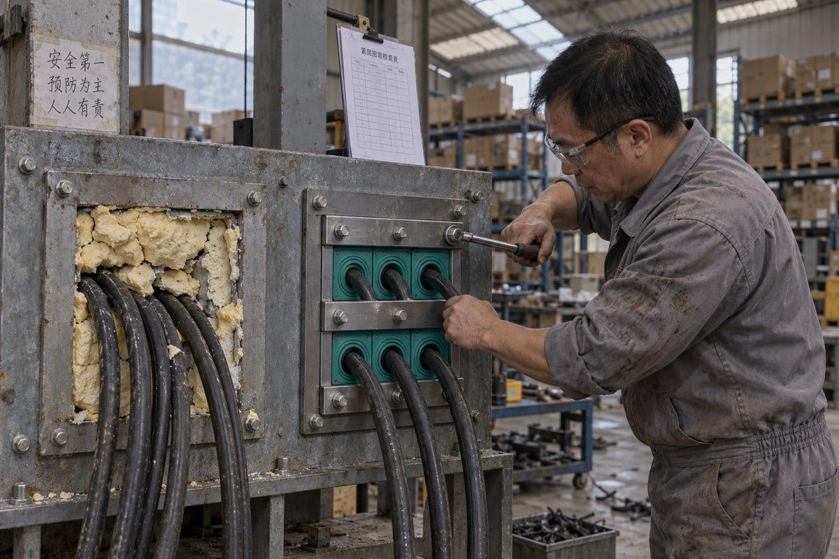
A buyer sent photos of foam-sealed penetrations in Zone 2 switchrooms. Multi cable transit in hazardous areas fails when treated as filler, so our factory builds it as a barrier.
Safety precautions for using multi cable transit in hazardous areas include confirming the zone classification first, selecting a system certified for that zone and gas group, fully compressing the seal, verifying gas-tight and watertight performance, and inspecting and re-torquing the transit throughout the asset’s life.
Those five steps sound simple. In practice, each one hides a place where projects go wrong. Below, I walk through the questions our European sourcing contacts ask most often, and I show the documents, checks, and trade-offs behind each answer.
What certifications and test documents should I request to verify MCT safety in hazardous areas?
During a BV factory audit, our QC team laid every test report on the bench. I noticed how quickly the auditor separated real hazardous-area evidence from generic brochures.
Request the ATEX or IECEx certificate matching your zone and gas group, the IEC 60079-0 test report, fire rating certificates such as A-0/A-60, IP68 ingress test results, gas-tight pressure test documents, and a material declaration for the EPDM sealing modules. Check certificate numbers against the issuing body.

The first thing I ask a buyer is not "how many cables?" It is "which zone?" A transit that is fine in a non-classified control room can be a liability one wall away. So the document review has to start with the classification, and then move to the product.
Start with the zone, not the product
Hazardous areas are split by how often flammable material 1 is present. For gases, the zones are 0, 1, and 2. For dust, the zones are 20, 21, and 22. Zone 1 and Zone 2 cover most cable-entry work I see in energy and infrastructure projects, but the difference between them still changes what you need to prove.
| Zone (gas / dust) | Presence of flammable material | What it means for the MCT |
|---|---|---|
| Zone 0 / Zone 20 | Continuous or for long periods | Highest level of proof; MCT usually assessed as part of the certified equipment |
| Zone 1 / Zone 21 | Occasional in normal operation | Product must carry certification for the zone, gas group, and temperature class |
| Zone 2 / Zone 22 | Abnormal conditions, short duration | Certification still required; barrier must stop migration to unclassified space |
A common mistake is to buy a "heavy-duty" transit and assume it covers everything. In a classified area, the MCT is part of the protection concept. It must maintain the enclosure's or wall's safety function, so it needs its own paper trail.
The document set I would put in a qualification file
| Document | Pourquoi c'est important | Ce qu'il faut vérifier |
|---|---|---|
| ATEX certification or IECEx standards certificate | Proves the assembly was assessed for explosive atmospheres | Zone, gas group, dust group, temperature class match your area |
| IEC 60079-0 test report | Shows the general Ex requirements were tested, not just claimed | Report references the same model numbers you are buying |
| Fire rating certificate (A-0 / A-60) | Keeps the fire boundary of the deck, bulkhead, or wall intact | Test orientation and frame type match your penetration |
| IP68 ingress test | Confirms the watertight seal under immersion | Depth and duration are stated, not just the IP code |
| Gas-tight pressure test | Confirms gas-tight integrity across the barrier | Pressure range is stated, for example 0.01–0.4 MPa |
| EPDM material declaration | Confirms halogen-free rubber and chemical compatibility | Compound name, hardness, and ageing data |
| Certificats de système qualité | Shows the factory can repeat the result batch after batch | ISO 9001 and IATF 16949 in force, factory approval from a body such as BV |
Some projects follow accepted engineering practice such as API RP 500 2 or RP 505 instead of, or alongside, ATEX. Global projects increasingly want several marks on one product, such as ATEX, IECEx, INMETRO, ECAS-Ex, and CCC. That breadth is useful, but I still tell buyers to check the certificate number with the issuing body. A scanned PDF is not proof.
At our Shaanxi plant, we share our fire, IP68, and gas-tight test documents on request. We also tell buyers plainly which scheme a given module configuration has or has not been assessed against. A skeptical purchasing engineer should expect that same directness from every supplier.
How do I confirm sealing performance meets IP68 and gas-tight requirements for my application?
Higher compression torque gives a tighter seal but risks crushing cable insulation. We weigh that balance every time we set the compression range for a new TSC module size.
Confirm sealing performance by matching the supplier's IP68 test depth and duration to your exposure, requesting a gas-tight pressure test report in the 0.01–0.4 MPa range, checking EPDM compatibility with site chemicals and hydrogen, and witnessing a pressure or leak test on a representative assembly.
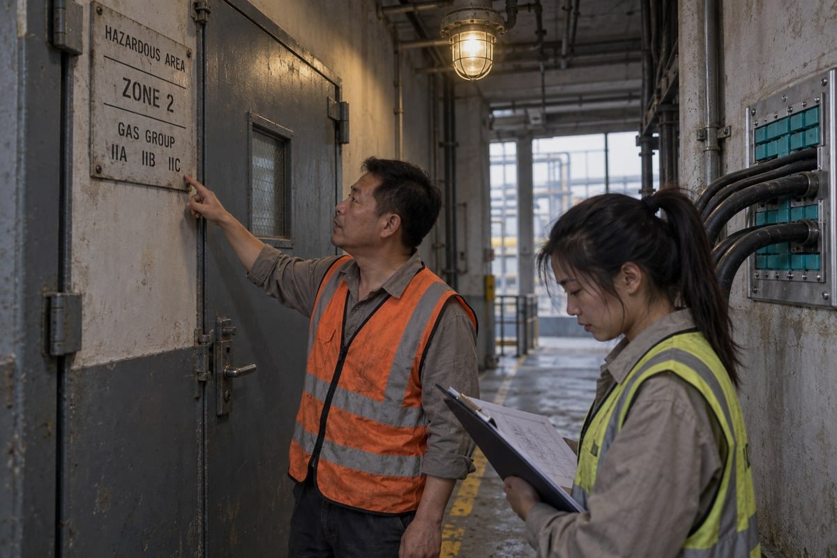
Sealing performance is where the marketing gap is widest. Every datasheet says "sealed." Very few say against what, for how long, and at what pressure. I break the question into four layers.
Layer 1: Water ingress
IP66 protection rating means the transit resists powerful water jets. IP68 means it survives continuous immersion under conditions the supplier must define. For an offshore platform, a BESS container in a flood zone, or a below-grade duct, I would insist on IP68 and ask for the test depth in meters and the duration in hours. Our modules are tested to IP68, and we state those conditions in the report rather than leaving the code to speak for itself.
Layer 2: Gas and vapor migration
This is the layer that matters most in a classified area. The rule is simple. A penetration between a hazardous and a non-hazardous space must stop gas or vapor from crossing under normal ambient pressure. Ask for a gas-tight test with a pressure figure. We test our TSR and TSC assemblies for watertight and gas-tight sealing in the 0.01–0.4 MPa range. Some codes also require internal seals inside the cable itself, in addition to the external barrier. Do not assume the frame alone satisfies that clause.
One growing concern is hydrogen. Hydrogen molecules are far smaller than hydrocarbon vapors. A seal that passes a methane test 3 may still permit hydrogen migration. If your project involves electrolyzers or hydrogen storage, ask the supplier directly about permeability data for their compound.
Layer 3: Fire and blast
Firestop sealing modules keep the fire boundary intact when the cable jacket burns away. Our modules are rated A-0 and A-60. Blast resistance is a separate structural question. Offshore platform safety cases often require the seal to survive a sudden overpressure event, so the frame, weld seams, and stay plates must be part of that calculation.
Layer 4: Material compatibility
| Exposure | Risk to the seal | Ce qu'il faut vérifier |
|---|---|---|
| Salt spray, marine air | Frame corrosion, loss of compression | Stainless steel or galvanized frame grade |
| Oils, solvents, amine treatment chemicals | Rubber swelling or hardening | EPDM chemical resistance data |
| Hydrogen service | Molecular permeation | Supplier permeability statement |
| Thermal cycling | Rubber settling, loosened bolts | Ageing test data plus a re-torque schedule |
Our step-core, halogen-free EPDM adapts to a range of cable diameters 4 within one module size. That flexibility helps sealing, because the rubber meets the cable across a broad contact band instead of a knife edge. But flexibility never replaces a witnessed test. When a European integrator qualifies us as a second source, I recommend they run a compression and leak test on the free validation sample under their own conditions.
What installation and maintenance precautions do I need to follow to keep MCT systems compliant on-site?
One lesson from our spare-module orders: many of them trace back to a cable added after commissioning that nobody re-compressed or recorded.
Route cables straight into the frame at 90 degrees, pack every spare slot with correctly sized blank modules, tighten the compression wedge system fully, then verify with a flashlight check and cable pull test. Afterward, inspect and re-torque periodically and control every cable change through a permit.

A certified product can still fail if the installer treats it like a pass-through. I have seen frames with a perfect certificate and a visible daylight gap. Installation quality is the third leg of the safety stool, and it is the one most often skipped.
The installation sequence I ask contractors to follow
- Check the frame. Confirm the cutout, weld seams, and stay plates match the drawing. Confirm frame material suits the environment. Stainless steel hardware belongs in marine and coastal work.
- Measure every cable. Choose the module size whose diameter range includes that cable. Our step-core modules cover a range, but the cable must sit inside it.
- Route cables straight. Each cable should enter the frame at 90 degrees. Angled entry loads one side of the module and opens a leak path on the other.
- Pack every gap. Adopt a strict no-gap rule. Spare slots 5 get correctly sized blank modules, packed tight. Loose spares are future leaks.
- Compress fully. The compression wedge system must be tightened to the specified figure. Incomplete compression is the single most common failure I see in field photos.
- Bond the frame. Grounding and earthing of the frame is part of ignition control in a classified area. Verify continuity to the structure.
- Verify. Run the QA checks in the table below before the wall is closed in.
| QA check | How to do it | What a failure looks like |
|---|---|---|
| Flashlight / daylight check | Shine a light from one side, look from the other | Any visible light means a gap |
| Cable pull test | Apply a firm hand pull on each cable | Any slippage means poor compression or wrong module size |
| Compression verification | Check the wedge or bolt position against the spec | Bolts not at full stroke, wedge not seated |
| Frame continuity | Measure resistance to earth | Open circuit or high resistance |
| Nameplate and record | Photograph the nameplate and module layout | Missing traceability for later audits |
Keeping it compliant after handover
Rubber settles. Steel expands and contracts. Both loosen compression over time, so a periodic visual inspection and re-torque should sit in the maintenance plan. Where the transit carries instrument cables next to power cables, compatibilité électromagnétique 6 (EMC) matters too. Some frames accept EMC shielding modules for sensitive signals in high-voltage zones. Each cable change after handover must go through change control. Some operators now use RFID-tagged blocks to keep a digital audit trail of who touched the frame and when. I like that trend. It turns an invisible seal into a tracked asset.
How can I validate a drop-in MCT replacement without compromising hazardous area safety approvals?
A sourcing manager in Germany once asked me a fair question: if your module fits the frame, does the frame's hazardous-area approval still hold? The honest answer takes some explaining.
Validate a drop-in MCT replacement by confirming dimensional compatibility with the 120-frame cutout using a cross-reference table, checking the replacement's fire, IP68, and gas-tight test documents, running a free validation sample through a witnessed compression and leak test, and having the site's hazardous-area authority approve the change before installation.

Let me deal with the objection head on. Certified MCT systems cost more than gland plates, mortar, or sand seals. A second source that is 40–60% cheaper than the incumbent sounds like a return to that cheap thinking. It is not, if you validate it correctly. The saving comes from factory-direct pricing and in-house tooling, not from removing tests. The trade-off you are actually weighing is qualification effort against long-term component cost. I try to make that effort small.
What "drop-in" does and does not mean
Dimensionally compatible means our TSR round assemblies and TSC square modules fit the cutouts of common 120-frame standards. It does not mean the original frame certificate transfers to our module. Certification belongs to the tested assembly. So a replacement module must bring its own evidence, and the site must document the change.
| Validation step | What we provide | What the buyer verifies |
|---|---|---|
| Dimensional match | Cross-reference table, existing model → DEWIN model, CAD/STEP files | Fit in the actual frame, compression stroke unchanged |
| Performance evidence | A-0/A-60 fire, IP68, gas-tight 0.01–0.4 MPa test documents | Test conditions cover the project requirement |
| Physical trial | Free validation samples | Witnessed compression, flashlight check, pull test, leak test |
| Quality repeatability | ISO 9001, IATF 16949, BV-approved factory | Certificates in force, batch traceability on the nameplate |
| Hazardous-area approval | Statement of which Ex schemes apply to the configuration | Site authority signs off the change under the area classification |
Avoid overdesign during the swap
A replacement is a good moment to add spare capacity. Be careful. Oversized apertures and too many spare slots make the watertight seal harder to hold, because more rubber-to-rubber joints exist. I advise buyers to plan spare capacity on real future cable schedules, then fill everything else with blanks.
Because we make our molds in-house, we can produce a custom module size for an odd cable diameter or a legacy frame. That avoids the classic failure where an installer forces a cable into the wrong module and calls it done. For private-label programs, the nameplate and documentation carry the integrator's identity, but the test data stays traceable to our production batch. That traceability is what lets an engineer defend the substitution during an audit years later.
Conclusion
Uncertified fill in a hazardous penetration is a hidden ignition path. Treat multi cable transit as a certified barrier: choose zone-rated systems, install to spec, and inspect for life.
Notes de bas de page
1. Overview of European safety standards for environments containing flammable gases or dust. ↩︎
2. Industry standard for the classification of locations for electrical equipment in petroleum facilities. ↩︎
3. Global standards for gas detection and material testing in industrial environments. ↩︎
4. International certification system for equipment used in explosive atmospheres. ↩︎
5. Provides the regulatory framework for certifying components in hazardous area applications. ↩︎
6. International standards for electrical equipment, including EMC requirements for industrial systems. ↩︎

 English
 Español de México
 Deutsch
 Français
 العربية
 Русский