
Shielding modules and E-house enclosures often fail the same way on sites fitted with our transit frames: the drawing says grounded, the meter says otherwise, and commissioning stalls.
Shielding modules ground properly with E-house enclosures when the module frame is bonded metal-to-metal to the entry plate, cable shields are terminated 360° at that plate, and the plate ties into the internal grounding busbar through a short, wide, low impedance path verified by continuity testing.
That sentence hides a lot of detail. Below I break it into four practical questions that our purchasing contacts in Europe ask most often ISO 9001 certified factory 1. Each section ends with something you can measure, request, or check on a drawing.
How do shielding modules maintain reliable ground continuity inside E-house enclosures?
During a frame inspection last year, one of our QC technicians found powder coat inside a customer-supplied cutout. The transit looked perfect. It read open circuit.
Shielding modules maintain ground continuity through three linked bonds: a conductive module layer that grips the bare cable shield around its full circumference, a compression unit that presses that layer against the metal frame, and a frame welded or bolted bare-metal to the E-house wall and grounding busbar.

An E-house is a metal box packed with drives, PLCs, switching power supplies, relays, and fibre or Ethernet gear. That mix makes electromagnetic compatibility 2 harder than in a single cabinet. The goal is simple to state. The enclosure and every shielding module must behave as one conductive system. In practice, that means every interface in the chain must be a real bond, not an accidental contact.
The three-bond chain
I think of the path as three bonds in series. If any one of them is poor, the whole path is poor. The table below shows where each bond lives, how it fails, and what we do about it on our production line and what we ask installers to do on site.
| Bond interface | Common failure | Practical fix |
|---|---|---|
| Cable shield to module insert | Jacket stripped too short or too long; braid only touches on one side | Strip precisely so the bare braid sits fully inside the conductive layer for 360° contact |
| Module to frame | Compression unit under-torqued; insert not seated on the stay plate | Torque the two hex bolts to the stated value and confirm the stay plates are flat |
| Frame to E-house wall and busbar | Paint, primer, or powder coat under the frame flange; zinc oxide on old plates | Grind the entry plate to bare metal, apply conductive anti-corrosion lubricant, bolt or weld the frame |
The frame is the piece we control most tightly. Our TSC and TSR frames are welded, and the flange is meant to be the continuation of the enclosure skin. Once the frame is bonded, the modules inside it only need to reach the frame, not the busbar directly.
Why pigtails and gaps break the path
Interference from a VFD is not a DC problem. It is a high-frequency problem. A pigtail wire between the shield and the frame adds inductance. At a few megahertz, that inductance is a high-impedance wall, and the shield current finds another route, usually through your signal ground. This is why a 360° shielded cable termination at the entry plate beats a long lead every time.
The same logic applies to gaps. The Faraday cage principle 3 only holds when openings are small compared with the wavelength of the highest interference frequency you expect. A transit frame that sits on paint is not a small opening. It is a slot the length of the frame perimeter. Some specifications also call for silver-plated or nickel-coated inserts, because skin effect pushes high-frequency current onto the surface, and plated surfaces keep surface resistance lower than bare steel in high-EMI rooms.
What grounding test data should I request before qualifying a shielding module supplier?
A sourcing engineer in Europe once asked us for the grounding certificate. We sent test sheets instead, because no single certificate exists for this.
Request four data sets: shield-to-frame resistance measured with a micro-ohmmeter after compression, frame-to-busbar resistance after installation, a torque-versus-resistance record showing stability after thermal cycling, and an independent EMI shielding effectiveness report for the module type across the frequency range of your VFDs and communications.

I prefer to hand buyers numbers on a page rather than adjectives in a brochure. The four data sets above are the ones that reveal whether a module actually keeps a low impedance path under real conditions. Here is what each one tells you, and what instrument produces it.
| Test data | What it proves | How it is measured |
|---|---|---|
| Shield-to-frame resistance | The conductive insert really grips the braid | Four-wire micro-ohmmeter, probe on braid and on frame flange |
| Frame-to-busbar resistance | The frame is bonded, not just bolted | Micro-ohmmeter between frame and the internal ground bus |
| Torque vs. resistance after cycling | The bond survives heat, vibration, and rubber relaxation | Repeat readings after defined thermal or vibration cycles |
| EMI shielding effectiveness | The module blocks fields, not just conducts DC | Shielded-room attenuation test over a stated frequency band |
A Z-axis verification you can run on site
The most useful check is the one the SERP results call Z-axis conductivity. It measures straight through the wall. I recommend this sequence during commissioning:
- Strip a short test length of one shielded cable inside the E-house.
- Place one micro-ohmmeter lead on the bare braid.
- Place the other lead on bare exterior skin near the frame.
- Record the value, then repeat on a cable at the far side of the frame.
- Compare against the limit in your project specification; many project specs set a bonding limit in the tens of milliohms.
Then check for ground loops. Measure AC voltage between the internal grounding busbar 4 and any separately grounded equipment frame. A reading well above zero says two ground references are fighting each other.
What I would treat with caution
Some ranking pages recommend ultrasonic leak detection and thermal imaging to find EMI leaks and hot bonds. Thermal imaging does catch high-resistance bolted joints under load, and I use it that way. Ultrasonic detection is designed for pressure leaks, not fields. It can support your gas-tight check, but it is not a substitute for electrical continuity testing. Ask the supplier which claims are backed by a report and which are marketing.
Can drop-in shielding modules match my existing E-house grounding design without rework?
Every cross-reference we publish weighs two things: the module must fit the 120-frame cutout exactly, and the frame must bond exactly as the original did.
Yes, drop-in shielding modules can match an existing E-house grounding design when they are dimensionally compatible with the 120-frame standard, use the same compression-unit height, and bond through the existing frame and entry plate; the grounding busbar, ground pads, and shield termination points stay unchanged.

Our second-source business only works because the grounding architecture of an E-house lives outside the module. The E-house specification we most often see asks for internal earthing with GI flats of suitable cross-section, ground pads that bond equipment frames and ground buses to the E-house frame at two opposite exterior locations, and a continuous path to earth. None of that changes when you swap a module. What changes is the rubber block and, in EMC variants, the conductive layer inside it. That is why we ship free validation samples with a model cross-reference table and STEP files. Your engineer can drop the sample into a spare cutout and run the same micro-ohmmeter check from the previous section before any purchase order.
What stays and what changes
| Element of the E-house grounding design | Changes with a drop-in module? |
|---|---|
| Entry plate and welded frame | No |
| Internal grounding busbar and GI flats | No |
| Exterior ground pads at two opposite locations | No |
| Compression unit and stay plates | Only if the height differs; ours match the 120-frame standard |
| Module insert and conductive layer | Yes, this is the part being replaced |
| Cable segregation and routing | No, but verify it anyway |
Buyer objection: single-point or both-end grounding?
Buyers sometimes worry that a new module will force both-end shield grounding when their design uses a single ground point. I resolve this objection with frequency, not preference. For low-frequency signals, one-end grounding still works and avoids loops. For VFD switching noise, fast transients, and comms above a few megahertz, both-end 360° bonding is the better default, provided the two ends sit on the same equipotential bonding network. A well-built E-house with bonded GI flats and ground pads is exactly that network. The module does not force the choice. It only makes 360° termination available at the entry.
Buyer objection: chassis bond or capacitive coupling?
A second objection concerns designs that couple the shield to circuit ground through a small capacitor to control ESD potential differences. This is a valid exception, and some drive manufacturers allow it for control cables. My position is direct. Chassis bonding at the enclosure wall is the first-line method in E-house practice. Capacitive or indirect grounding is a design exception, and it needs a written justification from the control system engineer. A drop-in module supports both, because the exception is wired downstream, not inside the transit.
One more point. Modular penetration seals cannot fix bad routing. Keep power, control, and instrumentation cables in separate frames or separate module rows, keep distance between them, and cross at right angles when you must. Perfect grounding cannot cancel noise re-injected by a power cable lying on a sensor cable.
Which certifications confirm a shielding module's grounding performance meets IP68 and fire-rating standards?
We learned early on that an IP68 report says nothing about ohms. Sealing certificates and grounding evidence are separate documents, and buyers deserve both.
No certification covers grounding, IP68, and fire rating together. IP68 proves ingress protection under IEC 60529, A-0/A-60 ratings prove fire integrity, and grounding performance needs separate electrical continuity test reports and EMI shielding effectiveness data, ideally issued by a BV-approved, ISO 9001 certified factory.
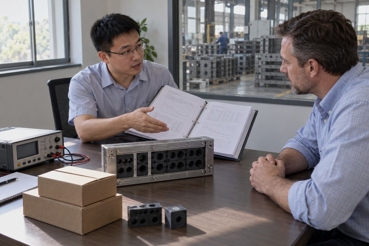
I want to be precise here, because this question causes real confusion in tenders. A certificate is only evidence for the property it tested. Our fire rating covers A-0 and A-60. Our ingress protection covers IP68. Our watertight and gas-tight sealing covers 0.01 to 0.4 MPa. All of those documents are available on request. None of them is a grounding certificate, and any supplier who says otherwise is stretching the paper.
What each document proves
| Document | Property it proves | What it does not prove |
|---|---|---|
| IP68 test report | Dust and water ingress under IEC 60529 5 | Any electrical bond |
| A-0 / A-60 fire test | Fire and heat integrity of the sealed penetration | Shield continuity during or after fire |
| Watertight / gas-tight report, 0.01–0.4 MPa | Pressure sealing of the compressed modules | EMI shielding effectiveness |
| Electrical continuity test sheet | Shield-to-frame and frame-to-busbar resistance | Field attenuation |
| Shielding effectiveness report | Attenuation across a stated frequency band | Sealing or fire performance |
| ISO 9001, IATF 16949, BV factory approval | The factory repeats its process consistently | Any single product value |
Why the gasket matters for both sealing and grounding
Between the frame flange and the E-house wall there is one component that touches both worlds: the gasket. A plain rubber gasket seals but insulates. Conductive gaskets seal and bond at the same time. Some suppliers now promote graphene-enhanced conductive gaskets for ultra-high-frequency transients. I have no objection, but I ask for the attenuation data before I believe the claim.
Galvanic corrosion prevention is the other half of this. A galvanized frame on a stainless plate, or a copper strap on aluminium, will corrode at the joint. Corrosion raises resistance year by year. Use compatible metals, add a conductive anti-corrosion lubricant, and keep the joint inside the IP68 envelope so moisture never reaches it. Our modules are halogen-free EPDM, so they do not release corrosive halogens that attack plated contacts in a fire.
Ask for the process, not just the sheet
When our customers audit us, the strongest evidence is not one test value. It is the routine. In-house mold making means insert dimensions are controlled at the source. IATF 16949 discipline means torque, plating, and dimensional checks are recorded per batch. Cable transit systems with that traceability give you a bond you can trust, and paperwork you can defend to your own quality department.
Conclusion
Floating shields stall commissioning and cost weeks. Bond the frame bare-metal, terminate shields 360°, measure every path, and ask us for cross-reference tables, test sheets, and samples.
Footnotes
1. Official page for the quality management standard required for module suppliers. ↩︎
2. Technical definition of the core challenge in E-house design. ↩︎
3. Scientific basis for the shielding effectiveness discussed in the article. ↩︎
4. Authoritative reference for the primary grounding component in electrical enclosures. ↩︎
5. Official source for the ingress protection standards mentioned for shielding modules. ↩︎



 English
  Español de México
  Deutsch
  Français
  العربية
  Русский