Electromagnetic shielding in multi cable transit structural design solves a real problem: every penetration we seal at our factory is a hole in the shield until we close it properly.
Electromagnetic shielding in multi cable transit structural design is achieved by a conductive metal frame, conductive sealing modules that contact each cable shield, and short, low-impedance bonding to the surrounding structure. Together they form a continuous path from cable shield to earth, extending the Faraday cage across the penetration.
That is the short version. The long version is about details. Frame thickness, weld quality, contact pressure, and grounding geometry all decide whether the shield works in the field. I will walk through each of them below, and I will show you what to ask a supplier before you sign a purchase order.
What Materials and Design Elements Give MCT Systems Effective EMI Shielding?
During a routine QC check on a welded frame batch last year, one of our inspectors flagged a cold weld seam. That seam would have been an EMI leak, not just a cosmetic flaw.
Effective EMI shielding in an MCT system comes from four elements: a rigid, welded metal frame, conductive sealing modules with copper or tinned-copper contact foils, 360-degree contact between each cable shield and the frame, and a compression unit that keeps contact pressure stable under vibration and thermal cycling.

I like to think of an EMC transit as a chain. The chain runs from the cable shield, through the module, into the frame, and out to the structure. Each link uses a different material. Each link can fail on its own. So let me break the chain into parts.
The frame is the backbone
The frame sets the boundary of the shield. Most EMC-rated transits use zinc-plated steel 1, stainless steel, or thick welded metal frames. Some product systems specify frames as thick as 10 mm and welded directly into the bulkhead. That thickness is not just for strength. It gives a wide, low-resistance path for interference currents. A welded frame also beats a bolted frame for continuity, because bolts can loosen and paint can creep between flanges. Some frame designs also use high-permeability steel to passively absorb low-frequency magnetic fields, which plated copper alone cannot do.
Conductive sealing modules close the gap around each cable
A standard halogen-free EPDM module, like our TSC or TSR step-core blocks, is an insulator. That is fine for fire, water, and gas sealing. For EMC openings, the module must carry a conductive layer. Manufacturers embed copper or tinned-copper foils inside the insert block so the foil wraps the cable shield on all sides. This 360-degree peripheral bonding is what removes high-frequency leakage paths. A single pigtail wire cannot do the same job.
Compression keeps the contact alive
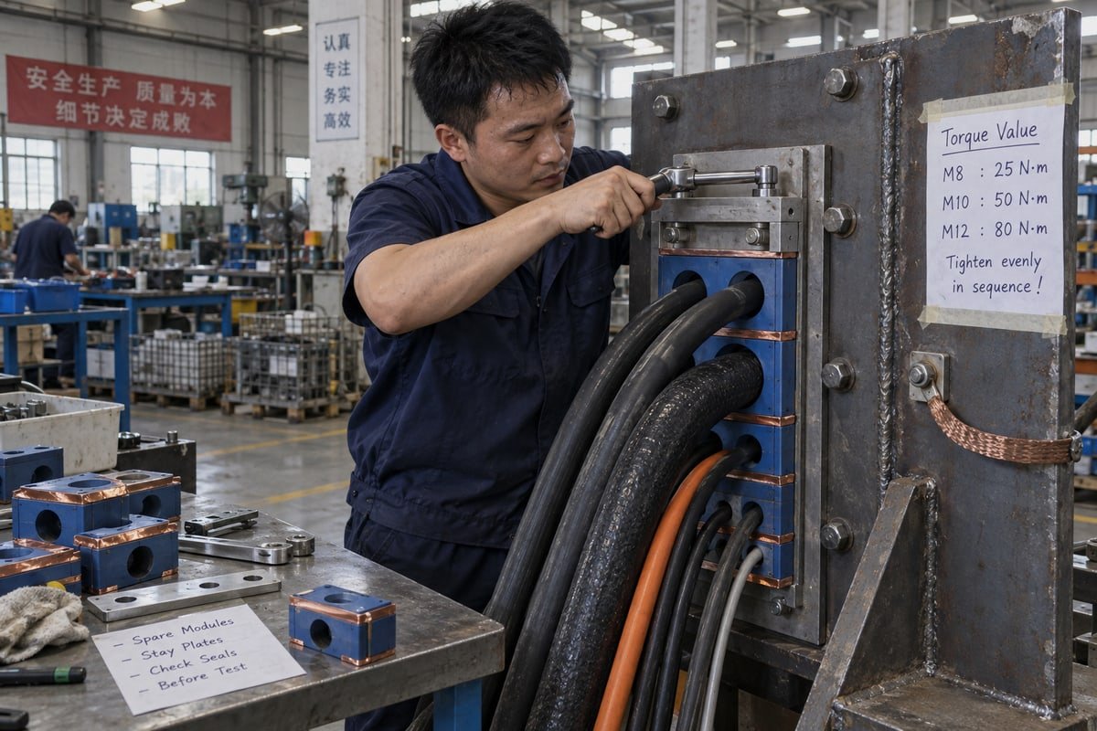
Contact pressure is the quiet hero. The compression unit at the top of the frame squeezes the module stack. That pressure holds the foil against the cable shield and against the frame walls. If the pressure drops from vibration or thermal expansion, tiny gaps open and shielding effectiveness falls. This is why we treat the compression unit and stay plates as EMC parts, not just sealing parts.
| Element | Common material | Shielding role | Sealing role |
|---|---|---|---|
| Transit frame | Zinc-plated or stainless steel, welded | Conductive boundary, Faraday cage extension | Structural anchor for the seal |
| Sealing module | EPDM core with copper or tinned-copper foil | Bonds cable shield to frame | Fire, water, gas seal around the cable |
| Contact tips / strips | Copper, tinned copper | 360-degree low-impedance contact | None |
| Compression unit | Steel wedge or bolt system | Maintains contact pressure | Maintains seal compression |
| Bonding strap | Wide braid or solid beam | Short path to earth | None |
You will also see newer ideas on the market. Carbon-nanotube-reinforced elastomers promise lightweight, broadband shielding with more flexibility than foil. I find the concept interesting, but I have not seen it displace copper foil in certified marine or infrastructure assemblies yet. Copper is still the proven choice for cable penetration seals that must pass both sealing and EMC tests.
Can I Verify EMI Shielding Performance Through Test Reports Before I Purchase?
A purchasing engineer in Germany once replied to our quote with a single line: "Send the test report or we do not continue." I respect that approach, and it changed how we prepare RFQ packages.
Yes. Ask the supplier for a shielding effectiveness test report for the complete assembly, not just the module. The report should state the test method, frequency range, attenuation levels in dB, grounding arrangement, and cable types used. Pair it with fire, IP68, and pressure test documents for the same product family.
Let me be direct about what test documents can and cannot tell you. Our standard document set covers what our modules are certified for: fire rating A-0/A-60, IP68 ingress protection 2, and watertight and gas-tight sealing from 0.01 to 0.4 MPa. These come from an ISO 9001 3 and IATF 16949 quality system in a BV-approved factory. We send them on request, before any order. EMI/RFI mitigation is a different test. It is measured on a whole assembly, and the result depends on how that assembly was grounded during the test. So I tell buyers to read EMC reports with three questions in mind.
Question one: what was measured?
Shielding effectiveness tests for enclosures and penetrations commonly reference methods such as IEEE 299 4 or IEC 61000-5-7. The report should name the method and the frequency sweep. Published application material for some module designs cites protection extending to 40 GHz and beyond. That is a strong number, but it only matters if your project needs it. A BESS container with a 4G telemetry link and a defense compartment have very different targets.
Question two: how was it grounded?
This is where many reports hide the real story. One referenced test summary reported over 40 dB attenuation with a direct conductive beam grounding path, versus around 20 dB when the same frame was grounded through a 20 cm wire. Same frame. Same modules. Half the performance. If the report does not describe the grounding and bonding method, ask for it.
Question three: does the sample match the product?
Test samples sometimes use ideal cable shields and perfect terminations. Your site will not. Check that the cable types, module sizes, and frame model in the report match what you are buying.
| Document | What it proves | What it does not prove |
|---|---|---|
| Shielding effectiveness report | Attenuation levels vs. frequency for the tested assembly | Performance with a different grounding path |
| Fire test certificate (A-0/A-60) | Fire integrity of the seal | Any EMC property |
| IP68 and pressure test (0.01–0.4 MPa) | Water and gas tightness | Any EMC property |
| ISO 9001 / IATF 16949 5 certificates | Process control and repeatability | Product performance limits |
| BV factory approval | Third-party audited production | Project-specific shielding results |
Some buyers push back here. They say EMC modules add cost and complexity, and that fire and watertight integrity are all their project needs. Sometimes they are right. But modern BESS containers, modular data centers, and switchgear rooms increasingly need physical sealing and EMI control in the same opening. Paying for a second retrofit later is more expensive than specifying the right module once. The test report is how you decide that with data, not with a sales pitch.
Will EMI Shielding in a Drop-In MCT Module Match My Existing Frame Standard?
The trade-off I weigh most often is simple. A drop-in module must fit the old frame cutout exactly, but it must also carry its own conductive path without relying on the old frame's condition.
A drop-in MCT module will match your existing frame standard if it is dimensionally compatible with the common 120-frame system, uses the same compression logic, and carries conductive contact foils that bond to the frame walls. Confirm fit with a cross-reference table, a validation sample, and a galvanic compatibility check between module contacts and frame plating.
Second sourcing is our core business. Our TSC square modules and TSR round assemblies are built to drop straight into existing 120-frame cutouts, and we back that with model cross-reference tables that map an existing model number to the matching DEWIN model. The cost saving is typically 40 to 60 percent against the original brand. But I never tell a buyer that dimensional fit alone guarantees EMC fit. Electromagnetic shielding in multi cable transit structural design depends on the interface between the new module and the old frame, and that interface has three parts.
Step one: confirm the mechanical envelope
The module height, width, and depth must match the frame's internal packing space. Our step-core design adapts to a range of cable diameters within one module size, which reduces the number of variants you stock. We supply CAD and STEP files so your engineer can check the packing plan before a sample ships.
Step two: confirm the conductive interface
For an EMC opening, the module's contact foil must press against bare, conductive frame walls. If your existing frame was painted inside after installation, or if the plating has corroded, the new module cannot fix that. This is where I ask buyers to send a photo of the frame interior. It saves a lot of email later.
Step three: check galvanic compatibility
Copper foil against zinc-plated steel in a damp marine or offshore environment can corrode. Tinned copper reduces the risk. Stainless frames behave differently again. A quick check of the metal pairing avoids a slow loss of electrical continuity that nobody notices until the next survey.
| Check | What we provide | What you confirm |
|---|---|---|
| Dimensional fit | Cross-reference table, CAD/STEP files | Frame cutout and packing space |
| Sample validation | Free validation sample | Fit, compression, cable diameter range |
| Conductive contact | Module contact specification | Frame interior is bare and conductive |
| Galvanic pairing | Contact material data | Frame plating and environment |
| Custom sizes | In-house mold making | Non-standard cable or frame dimensions |
Some engineers argue that a continuous welded metal enclosure will always outperform a modular transit. In pure physics terms, they have a point. A solid wall has no seams. But a solid wall also has no cables through it. The modular transit is the compromise that lets cables pass while keeping Faraday cage integrity 6, and the price of that compromise is installation discipline. A drop-in module from a qualified second source does not change that equation. It only changes what you pay for the module and how quickly spare sealing parts arrive.
How Do I Confirm EMI Shielding Continuity Across Frame, Modules, and Cable Interfaces?
The hardest lesson our technical team learned came from a site where everything was installed correctly except one detail: the ground strap was a thin, 30 cm wire. The shield looked perfect on paper and leaked in practice.
Confirm shielding continuity with a four-point check: verify the frame is welded or bonded bare-metal to the structure, verify every cable shield is terminated 360 degrees inside a conductive module, verify compression torque is at specification, and measure bond resistance across frame-to-structure and shield-to-frame paths with a low-resistance meter.

Continuity matters more than material. I repeat this to every EPC procurement team that asks about EMC transits. A highly conductive frame with one bad joint performs like a cheap frame. So I treat continuity as a process, not a property. Here is the sequence we recommend at handover.
- Inspect the frame-to-structure bond. Look for full weld seams or bare-metal bolted contact. Paint under a flange is a fault. Short, wide, direct paths beat long thin wires, because inductance rises with length and kills high-frequency attenuation levels.
- Inspect each cable interface. Every shielded cable must sit in a conductive module with the outer jacket stripped so the foil meets the braid. One unterminated shield creates a leak and can drive asymmetrical currents into neighboring cables.
- Check compression. Torque the compression unit to the specified value. Under-compression opens gaps. Over-compression can deform the EPDM and shift the foil.
- Measure. Use a four-wire low-resistance meter from a cable shield to the frame, and from the frame to the structure. Record the values. Repeat at the next maintenance cycle and compare.
Grounding philosophy: direct bond or equipotential network?
Buyers sometimes ask which is correct. Some engineers prefer bonding the frame straight into the bulkhead. Others build a wider equipotential network across the room. Both aim at the same result. The practical worry is impedance and ground loops. My advice is to bond the frame directly at the penetration, and then let the equipotential network handle the rest. Do not rely on the network alone to ground the transit.
Separate services to reduce internal coupling
Power, control, and instrumentation cables should not share one opening if you can avoid it. Separate frames, or a combined frame with internal separation, reduce crosstalk. Some vendors now market AI-optimized cable positioning to calculate ideal spatial layouts inside the transit. In my experience a clear packing plan, drawn by an engineer and checked against the module inventory, delivers most of that benefit.
| Checkpoint | Pass condition | Common failure |
|---|---|---|
| Frame to structure | Welded, or bolted bare-metal with wide strap | Painted flange, long thin ground wire |
| Cable shield to module | 360-degree foil contact on exposed braid | Jacket not stripped, pigtail only |
| Module to frame | Foil pressed to bare frame wall | Painted or corroded frame interior |
| Compression | Torque at specification | Loose after vibration or thermal cycling |
| Service segregation | Power and signal in separate openings | Mixed cable types in one frame |
Newer concepts are appearing here too. Real-time impedance monitoring sensors inside the transit could flag galvanic corrosion or mechanical fatigue before shielding degrades. Fractal-based conductive geometries are being discussed for sub-THz frequencies with 6G in mind. I watch these developments, but I have not seen them in a certified assembly I could sell with a test report. For now, electromagnetic pulse protection and everyday EMI/RFI mitigation both still depend on the same four checks above, done by a person with a torque wrench and a meter.
Conclusion
Every cable opening is a shield gap. Left alone, it leaks EMI into your most sensitive rooms. A properly framed, bonded, and tested transit closes it for good.
Electromagnetic shielding in multi cable transit structural design is never one component. It is a coordinated system: a welded conductive frame, conductive sealing modules that wrap each cable shield, a compression unit that keeps contact pressure stable, and a short, wide bond to the structure. Ask for assembly-level test reports with the grounding method stated. Confirm drop-in modules against a cross-reference table and a free validation sample. Then verify continuity with a meter, not with assumptions. Do that, and your penetration becomes a controlled conductive interface instead of a weak point.
Footnotes
1. Standard-setting body for materials like the zinc-plated steel used in transit frames. ↩︎
2. IEC page explaining the ingress protection ratings for dust and water resistance. ↩︎
3. Official site for the quality management standard used in the manufacturing process. ↩︎
4. Standard for measuring shielding effectiveness of enclosures, used for testing MCT assemblies. ↩︎
5. Authoritative source for the automotive quality standard cited for process control. ↩︎
6. Explains the physical principle of electromagnetic shielding mentioned in the article. ↩︎



 English
  Español de México
  Deutsch
  Français
  العربية
  Русский