One skipped step in the standard installation process for multi cable transit systems can void a fire rating IATF 16949 1. Our factory sees the returned frames. Here is the full sequence.
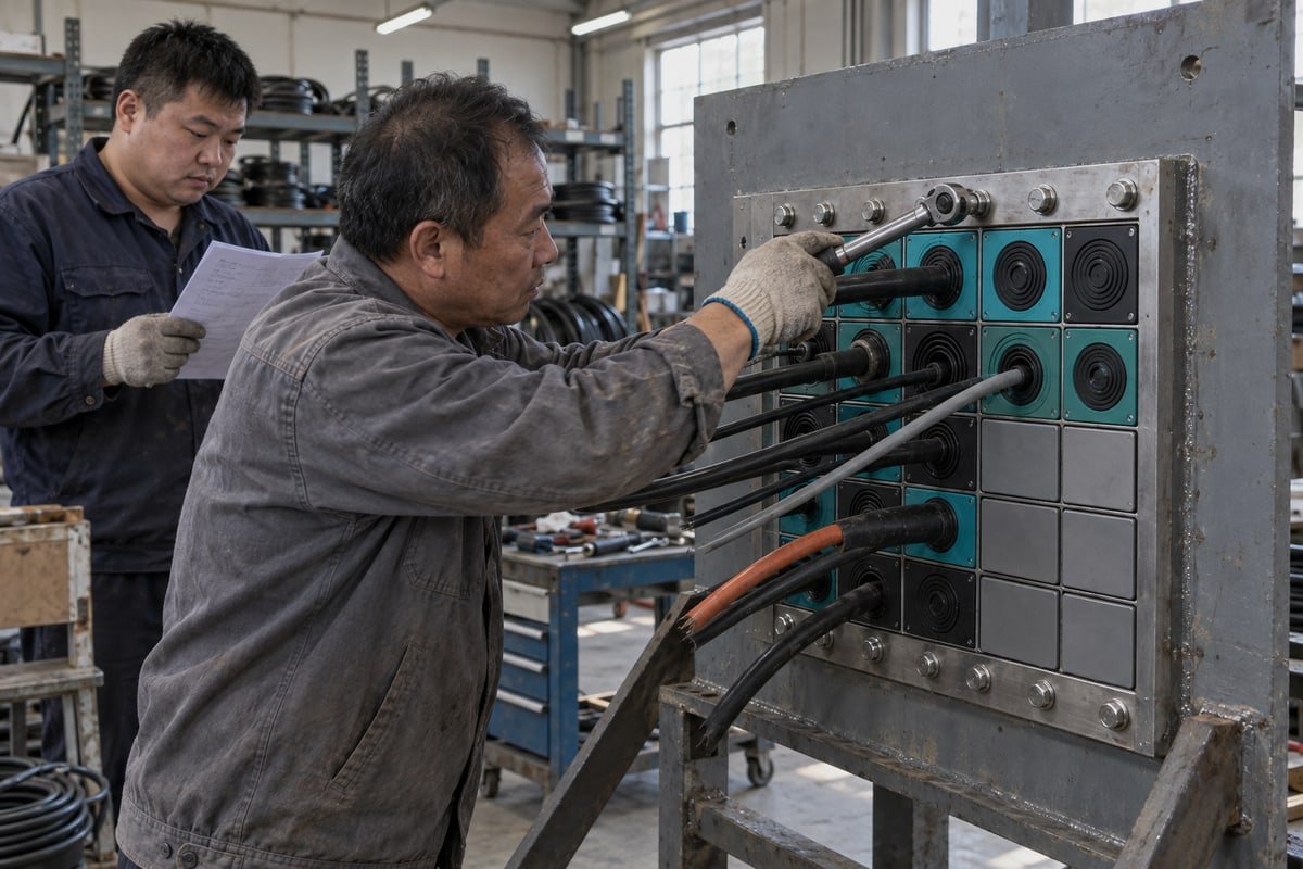
The standard installation process for multi cable transit systems has six steps: plan the transit layout, mount the frame by welding or bolting, prepare and route cables, insert sized sealing modules with stay plates, compress with a wedge to specified torque, then inspect and test for watertight and fire-rated performance.
Each of those six steps has its own failure points. I will walk through the four that cause the most trouble for our customers: the cutout, module sizing, compression torque, and final validation.
What steps are involved in preparing the frame cutout before I install an MCT system?
A sourcing engineer in Germany once sent us a cutout drawing that was slightly undersized. We caught it before the frames shipped. Cutout prep starts on paper.
Preparing the frame cutout involves confirming the transit plan, measuring wall or bulkhead thickness, cutting the opening to the frame's outer dimensions plus manufacturer tolerance, cleaning and squaring the edges, checking for level and plumb, then anchoring the frame by welding, bolting, or casting before any cable is pulled.

Start with the transit plan, not the grinder
The transit plan is the drawing that fixes frame position, cable count, and module layout. I ask buyers for it before I quote. It tells me the wall thickness, the frame type, and whether the opening sits in a fire-rated or watertight boundary. Our TSC frames follow common 120-frame standards. So the cutout dimensions match what most installers already know. We also send CAD/STEP files, so the cutout can be drawn straight from the model instead of from a paper sketch.
Cutting and cleaning the opening
- Mark the opening from the frame drawing. Add the tolerance stated on the datasheet.
- Cut the opening. Keep the edges square. A tapered edge leaves a gap behind the flange.
- Remove slag, paint, and burrs. Cable sealing modules seal against clean metal, not against debris.
- Check level and plumb. A twisted frame loads the compression wedge unit 2 unevenly later.
- Dry-fit the frame. Confirm the flange sits flat on all four sides.
Three ways to anchor firestop transit frames
| Method | Typical substrate | Where we see it most | Watch point |
|---|---|---|---|
| Welding | Steel bulkhead, deck, container wall | Marine and offshore applications, BESS containers | Weld fully around the frame; grind spatter off the inside faces |
| Bolting | Panels, enclosures, thin walls | Switchgear, modular data centers, retrofits | Fit the gasket; tighten bolts in a cross pattern |
| Casting in | Concrete walls and floors | Substations, plant buildings | Protect the frame opening from concrete ingress |
Two things buyers often forget
First, prefabrication. Many of our BESS container customers weld frames in the workshop, fit a temporary blank, and ship. The final cable work happens on site. This is faster and more consistent than field welding.
Second, spare capacity planning. Cutting a rated wall twice is expensive. If the project will add cables in two years, size the frame for them now and fill the empty rows with blank modules. Note that some sealant-based transit systems require a minimum 15 mm sealant layer. Modular MCT frames do not rely on sealant for the seal, so the cutout accuracy carries more weight.
How do I select the correct module size and insert configuration for my cable diameters?
Every module size is a trade-off between adaptation range and compression travel. We weigh this each time we cut a new step-core mold in Shaanxi.
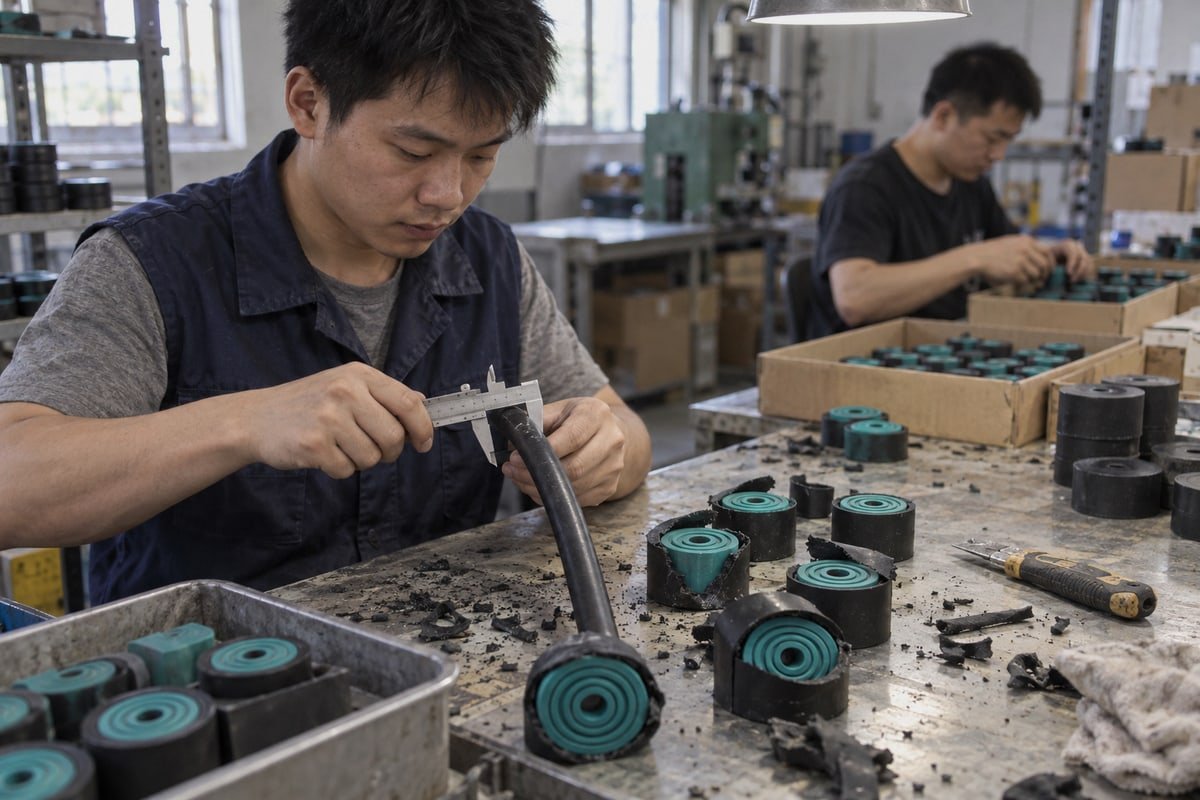
Select module size by measuring each cable's outer diameter with calipers at several points, choosing the module whose adaptation range brackets that diameter, peeling step-core layers until the cable fits snugly, filling unused space with blank modules for spare capacity, and inserting a stay plate between every row.
Cable diameter measurement comes first
Most sizing errors trace back to a bad measurement. Cable datasheets list a nominal diameter. The real cable can be a millimetre larger or smaller. Ovality adds more error. So I tell installers to measure the actual cable, not the catalogue.
| Step | Tool | Acceptance rule |
|---|---|---|
| Measure outer diameter | Vernier caliper | Take three readings at 120° spacing; use the average |
| Check ovality | Same caliper | If max minus min exceeds the module step, treat as the larger size |
| Match to module range | Manufacturer selection chart | The measured diameter must sit inside the range, not at its edge |
| Record the result | Transit plan | Write the module code next to each cable ID |
How step-core modules adapt
Our TSC square modules and TSR round assemblies use halogen-free EPDM 4 with concentric peel-off layers. You strip layers until the remaining core matches the cable. Stop when the cable just slides in with light resistance. Peel one layer too many and the module cannot compress enough to grip. Peel one too few and the cable is crushed. This is the trade-off I mentioned above. A wide adaptation range is convenient, but every layer removed reduces the rubber left to compress.
Building the stack
Fill each row from the bottom. Put a stay plate between every row. Stay plates are not optional spacers. They keep the rows aligned so the compression wedge unit pushes on all modules evenly. Empty positions get blank modules, never loose rubber or foam. For fibre-optic cables, use a guide sleeve inside the transit so the bend radius is protected where the cable exits the frame.
A note on second sourcing
Because our modules are dimensionally compatible with common 120-frame standards, a buyer who already has an installed frame can use our model cross-reference table to map their current module code to a DEWIN code. We send free validation samples so the fit can be confirmed on the bench before a purchase order. That saves a sourcing engineer from guessing.
What torque and compression specifications should I follow to achieve a certified watertight seal?
During a QC run on our TSC modules last year, one wedge came back with a stripped bolt. The installer had guessed the torque. That is the lesson here.
Follow the manufacturer's stated torque for your compression wedge unit—some systems specify around 5–8 Nm with a calibrated torque wrench—tighten bolts evenly in stages, apply approved lubricant for cable seals first, and stop when the modules show full, uniform compression with no daylight visible through the transit.

Why compression is the step that fails most
Incomplete compression is the most common failure point in transit installations. It is also the easiest to hide. A half-tightened wedge looks finished from a metre away. The gaps only show when water or smoke finds them. So this step needs a written procedure, not a feel for "tight enough."
The sequence we teach
| Stage | Action | Check before moving on |
|---|---|---|
| 1. Lubricate | Apply the approved lubricant for cable seals to module faces and frame inner walls | Thin, even film; no dry patches |
| 2. Seat the stack | Confirm every stay plate is flat and every module is fully pushed back | No module proud of the frame face |
| 3. Insert the wedge | Slide the compression wedge unit into the top space | Wedge sits square, not cocked |
| 4. First pass | Tighten bolts to roughly half the specified torque, alternating sides | Stack moves down evenly |
| 5. Final pass | Tighten to the datasheet torque with a calibrated wrench | Wrench clicks on both bolts |
| 6. Settle and recheck | Wait, then re-torque once | No further movement |
The lubricant matters more than people think. It lets the rubber flow into the gaps around each cable during compression. Without it, the modules bind against the frame walls and the lower rows never see full load.
The objection I hear from installers
Contractors tell me the process must be fast and cheap. Certification bodies tell me it must be done by trained people to a written spec. Both are right. The physical work on a well-planned transit takes minutes. The discipline is in the torque value and the record of it. Digital torque-logging wrenches now capture each bolt reading with a timestamp. That gives the EPC a verifiable installation record without slowing the crew down. Some suppliers are also fitting IoT sensors to wedges for remote monitoring of seal pressure. We treat that as a useful add-on, not a replacement for the torque wrench.
What our test data supports
Our modules are tested watertight and gas-tight from 0.01 to 0.4 MPa when installed at the specified compression. That number only holds if the wedge reaches its rated torque. Under-torqued, the rating drops with it. The test documents are available on request, and they state the compression condition clearly.
How can I validate my installation meets IP68 and fire-rating requirements before final sign-off?
Our BV factory approval taught us one thing: a certificate on the module means nothing if the field test is skipped. Validation closes that gap before sign-off.
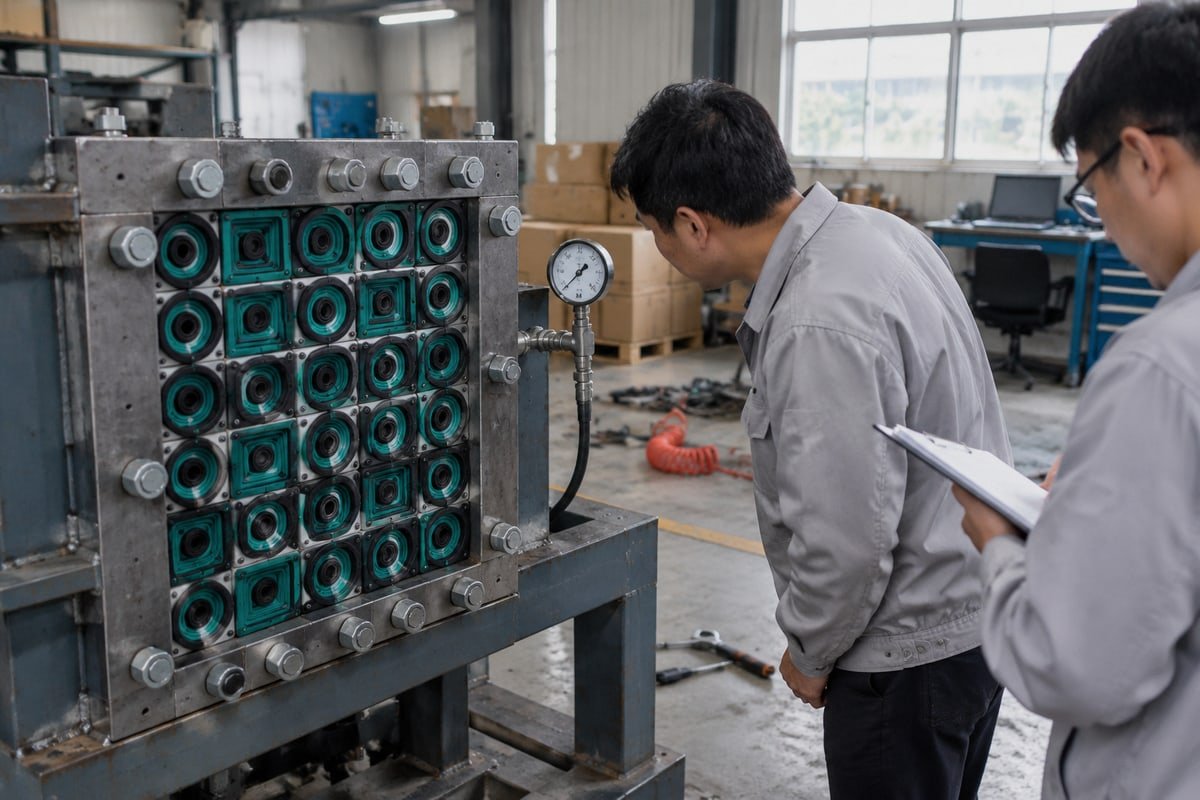
Validate the installation by checking wedge torque against the log, doing a daylight test for gaps, pulling each cable to confirm grip, running an air-hose or pressure test for watertight and gas-tight boundaries, and matching the installed configuration to the tested certificate for A-0/A-60 fire rating and IP68.
Field tests that catch real defects
| Test | What it finds | Pass condition | Where it is required |
|---|---|---|---|
| Torque log review | Under-compression | Every bolt at datasheet value | All installations |
| Daylight / torch test | Gaps between modules or around cables | No light passes through the transit | All installations |
| Pull test | Wrong module size, low compression | Cables do not slip under firm hand pull | All installations |
| Air-hose test | Leak paths in watertight, air-tight, oil-tight boundaries | No bubbles or pressure loss | NAVSEA guidance for new or disturbed transits |
| Pressure test | Seal performance under load | Holds within the 0.01–0.4 MPa tested range | Marine and offshore applications, pressurised rooms |
Fire rating compliance is a configuration check
Fire rating compliance is different from the leak tests. You cannot burn-test a finished wall. Instead, the inspector compares the installed transit with the tested configuration on the certificate. That means the same frame type, the same module family, stay plates in every row, and the wedge at rated compression. Our A-0 and A-60 test reports describe that configuration. If the installer substituted a foam filler or skipped a stay plate, the installation is outside the certificate, even if it passed the air test.
Documentation for the sign-off pack
A sourcing manager once asked me what to put in the handover file. My answer is short. Include the transit plan with module codes, the torque log, the test results, and our certificate set. We run ISO 9001 5 and IATF 16949 systems, and the factory is BV-approved, so the paperwork maps cleanly onto what an EPC quality team expects. For repeat projects, augmented reality overlays are starting to appear that show module placement on a tablet during the build. They reduce layout errors, but the inspector still signs the paper.
When validation fails
Do not add sealant on top. Loosen the wedge, find the wrong module or missing stay plate, correct it, re-torque, and re-test. A modular transit is designed to be opened. That is its advantage over a poured penetration.
Conclusion
Skipped steps cost certifications. A disciplined multi cable transit installation—plan, mount, size, compress, verify—protects them. Request our cross-reference tables and validation samples to start qualification.
Footnotes
1. The official site for the IATF 16949 automotive quality standard, relevant to the factory’s certifications. ↩︎
2. Wikipedia entry for cable transits, explaining the mechanical compression components used to seal penetrations. ↩︎
3. The IMO sets the international standards for fire-tested configurations in marine and offshore safety certificates. ↩︎
4. Technical reference for EPDM rubber, the material used for the modular seals discussed in the article. ↩︎
5. Official ISO page for the quality management standard mentioned in the manufacturer’s documentation section. ↩︎



 English
 Español de México
 Deutsch
 Français
 العربية
 Русский