
A multi cable transit fails quietly. On our test rig I have watched a well-packed frame leak because one compression bolt was cranked past spec. Torque, not parts, decided it.
To install a multi cable transit, mount the frame, route cables, pack lubricated sealing modules largest first with stayplates between rows, insert the compression unit, then tighten its bolts alternately with a torque wrench to the manufacturer’s value—commonly 8–20 Nm—never beyond it.
That short answer hides several decisions. Below I walk through the installation sequence, explain where the compression unit torque number actually comes from, address second-sourcing with our 120-frame-compatible modules, and show how to prove the finished penetration meets IP68 and fire-rating requirements.
What steps do I need to follow to install an MCT frame and sealing modules correctly?
Last year a QC engineer at our Shaanxi plant rejected a demo frame. Module sizes were right. The order was wrong. Small blocks sat low and the stack rocked.
Install an MCT by cleaning and mounting the frame with its gasket, routing cables, verifying each cable diameter, peeling module layers to a 0.1–1.0 mm gap, lubricating them, packing largest modules first, adding stayplates between rows, then fitting and tightening the compression unit evenly.

The sequence matters more than any single step. I break it into three phases, because each phase has its own failure mode.
Prepare the frame packing area
Start with the frame. Remove paint, weld spatter, dirt, and grease from the inside faces. A dirty frame packing area gives the modules an uneven surface to grip, and it also breaks the earth path if the frame is part of your bonding scheme. If the frame is surface-mounted, fit the gasket or apply sealant on the contact faces for gas-tightness, and attach the earth cable to the earth stud where one is provided. Then fasten the frame. Note that frame fasteners have their own torque. One published example for an Ex-rated cabinet frame calls for counter-frame nuts tightened crosswise in small steps to 4 Nm. That number is for the frame. It is not the compression unit value, and mixing the two is a common site error I return to in the next section.
Pack the cable sealing modules
Route the cables or pipes through the opening. Then perform cable diameter verification on every cable with a caliper, not from the cable datasheet alone, because jacket tolerances drift. Our TSC series modules use a step-core design in halogen-free EPDM 1, so one module size covers a range of diameters. You peel the inner layers until the two halves show a 0.1–1.0 mm gap when held against the cable. Too tight and the halves will not close; too loose and the seal relies entirely on compression. Apply lubricant for sealing blocks to every module face, the frame interior, and the compression unit itself. Skipping lubrication is the most frequent cause of half-seated modules that later show up as a weep during pressure testing.
Pack according to the approved filling plan. Insert from the back side, and put the largest modules in first. Large modules at the bottom give the stack a stable base and let smaller modules fill the remaining rows without tilting.
Stayplate installation and pre-compression
Insert a stayplate between every row of modules. Stayplate installation is what gives the transit its mechanical anchorage. Under a pressure event, the stayplates keep the rows from shearing and stop cables from pulling out. After the final row, use a pre-compression tool or wedge to consolidate the stack. This creates the clearance you need to slide in the final compression unit without forcing it.
| Phase | Key actions | Common mistake |
|---|---|---|
| Frame preparation | Clean, gasket or sealant, earth stud, fasten frame to its own torque | Using the compression torque on frame nuts |
| Cable and module packing | Measure cables, peel to 0.1–1.0 mm gap, lubricate, largest first | Peeling from the label side or skipping lubricant |
| Stayplates and pre-compression | Stayplate between every row, pre-compress, insert wedge | Leaving out stayplates to save time |
| Final compression | Tighten alternately to spec, inspect bulge | Overtightening past the stated maximum |
Only after all of this do you touch the compression unit bolts.
How do I know the correct compression unit torque for a watertight and gas-tight seal?
Every wedge we design forces one trade-off: enough compression to hold 0.4 MPa, yet little enough that a technician can reopen the transit five years later.
The correct compression unit torque comes only from the manufacturer's installation sheet for that frame and bolt size. Published values range from about 8 to 20 Nm, with Roxtec capping bolts at 20 Nm. Tighten alternately, stop at spec, and never apply frame-fastener torque to the wedge.
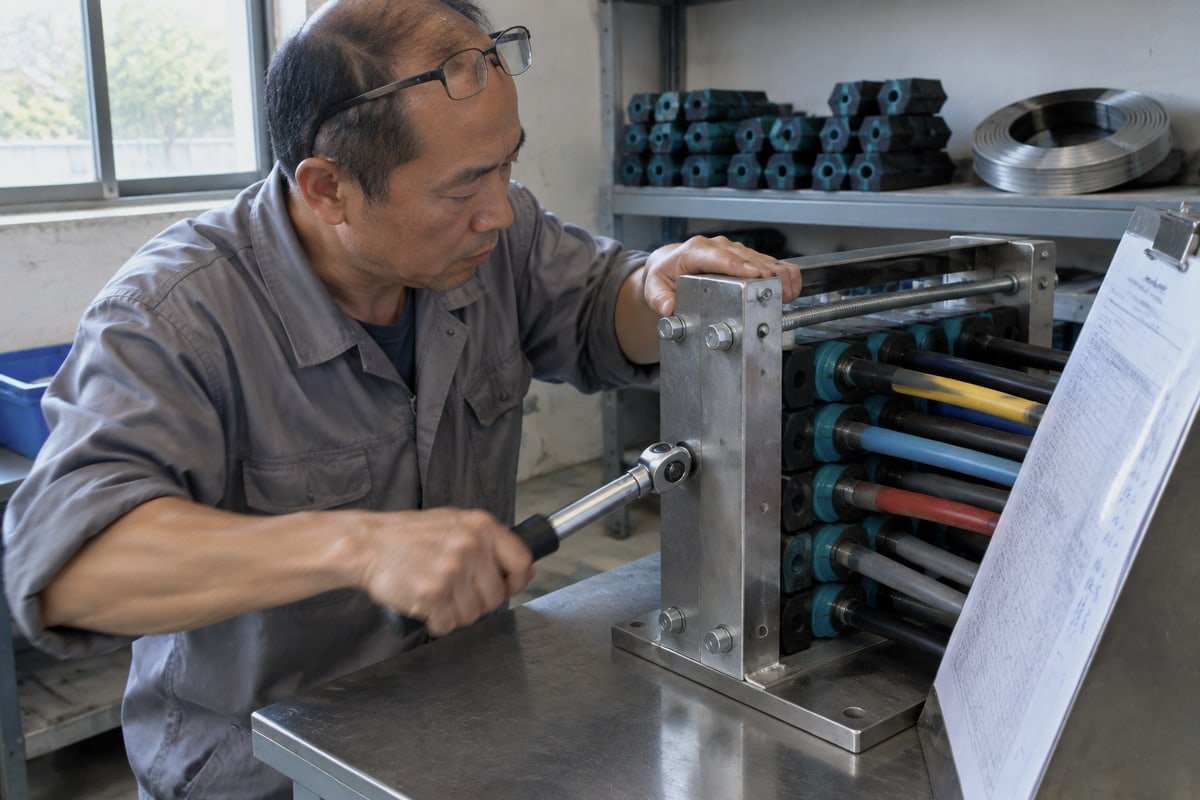
Sourcing engineers often ask me for "the MCT torque number." I understand why. A single value fits neatly on a work instruction. But the honest engineering answer is that the number is conditional on the compression wedge assembly design, the bolt thread size, and the frame series. The table below shows how widely published figures already differ.
| Source or component | Torque value | What it applies to |
|---|---|---|
| Roxtec compression unit bolts | Max 20 Nm | Compression unit only |
| Roxtec HD 32 Ex counter-frame nuts | 4 Nm, crosswise, small steps | Frame mounting, not compression |
| M6 bolts on related sealing hardware | 5–8 Nm | Fittings and frame accessories |
| M8 bolts on related sealing hardware | 20–25 Nm | Fittings and frame accessories |
| Typical range across ranking guides | 8–20 Nm | Compression unit, brand-dependent |
Why there is no universal number
The compression unit is not a fastener. It is a functional mechanism. A one-piece wedge compresses and decompresses the module stack by turning its front screws, so the torque you apply sets the actual sealing pressure on the rubber. A 20 Nm figure that is correct for one brand's M8 wedge screw can be 250 percent too much for a small M6 compression unit. This is why I push back on forum advice that gives one all-purpose value. The correct torque wrench settings come from the installation sheet shipped with the specific product, and we print that sheet for every DEWIN compression unit and include it in the export documentation pack.
Tightening sequence protocol
Tighten the bolts alternately. Give each bolt a partial turn, move to the other, and repeat until you reach the stated torque or the full-stop condition the sheet describes. This tightening sequence protocol distributes force evenly across the frame. If you run one bolt down first, the wedge tilts, one side of the stack over-compresses, and the opposite side can leave a gap. Watch the rubber. Correct compression shows as a visible, even bulge along the module edges or as engagement of any built-in indicators.
What over-tightening does
Exceeding the maximum does not make the seal "extra tight." It distorts the elastomer, can strip threads, and can pinch the cable jacket. It also makes future re-entry much harder, because the modules cold-flow into the stressed shape. Under-tightening is the opposite failure: the stack holds under a dry test and weeps under sustained pressure. Both errors trace back to the same cause, which is guessing instead of reading the sheet.
Can I use my existing 120-frame hardware when installing DEWIN sealing modules?
A sourcing manager for a BESS container builder in Germany asked me this exact question, with a spreadsheet of 120-frame part numbers open on the call.
Yes. DEWIN TSC square modules and TSR round assemblies are dimensionally compatible with common 120-frame standards, so they fit existing frame cutouts, stayplates, and compression units. Confirm fit with our model cross-reference table and a free validation sample before switching production.
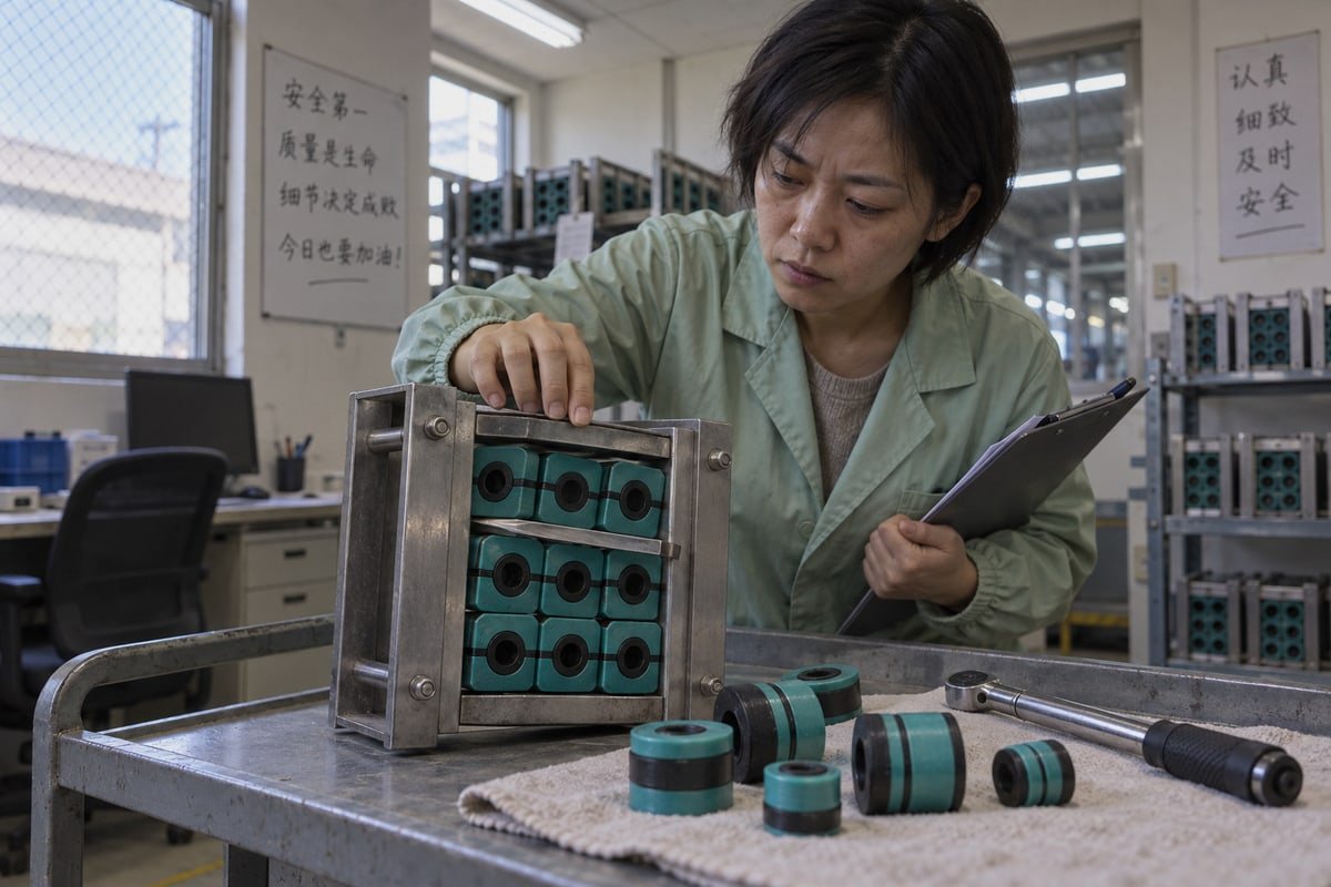
I want to be precise about what "drop-in" means, because European purchasing engineers read spec sheets before they reply, and vague compatibility claims cost us credibility. Below is the qualification path we walk through with every new OEM or EPC account.
| Qualification item | What you check | What we provide |
|---|---|---|
| Module footprint | Width, height, and depth against the 120-frame packing area | Model cross-reference table (existing model → DEWIN model) |
| Cable diameter range | Step-core layers cover your measured cable OD | Datasheet per module size, CAD/STEP files |
| Stayplates and compression unit | Existing hardware seats correctly with our modules | Free validation samples for a trial pack |
| Certification | IP68, A-0/A-60, watertight and gas-tight 0.01–0.4 MPa | Test documents on request, BV-approved factory |
| Quality system | Process control for repeat batches | ISO 9001 and IATF 16949 systems |
What drop-in compatibility covers
Dimensional compatibility means our cable sealing modules occupy the same space as the module they replace. Your frame stays on the wall. Your stayplates stay in the stack. Your compression unit stays in the top, bottom, or middle position you already use. The buyer I mentioned ran a mixed frame on a spare container, half existing modules and half DEWIN, and packed it with the same filling plan. That is the practical test I recommend, and it is why we ship validation samples free.
What drop-in compatibility does not cover
Compatibility of dimensions is not permission to ignore torque. When you keep an existing compression unit, you follow that unit's torque sheet, because the wedge geometry and screw thread belong to that unit. When you switch to a DEWIN compression unit, you follow ours. The module brand does not change the torque rule; the compression hardware does. I state this in every technical handover because it is the single most likely point of confusion during a second-source transition.
Cost, lead time, and spare capacity management
The commercial case is 40–60% lower component cost with the same certified performance, which is why integrators qualify us as a second source rather than a replacement. Since we make molds in-house, custom module sizes and private-label runs are feasible without a trading company in the middle. For spare capacity management, we recommend packing every frame with a defined percentage of blank modules. Later additions then only require decompressing the wedge, swapping a blank for a peeled module, and re-torquing to spec, without dismantling the penetration. Fast delivery of spare sealing modules is part of the reason lead-time reliability matters as much as price to the teams we serve.
How do I verify that my installed MCT system meets IP68 and fire-rating requirements?
Type approval taught our team a hard lesson: a certificate proves the design. It proves nothing about the frame your electrician packed on Tuesday.
Verify an installed MCT by matching frame, modules, and compression unit to the certified configuration, checking torque with a calibrated wrench, inspecting for rubber bulge and full packing, then testing tightness with pressure, soap solution, or ultrasonic leak detection and recording results against the IP68 and A-0/A-60 documents.
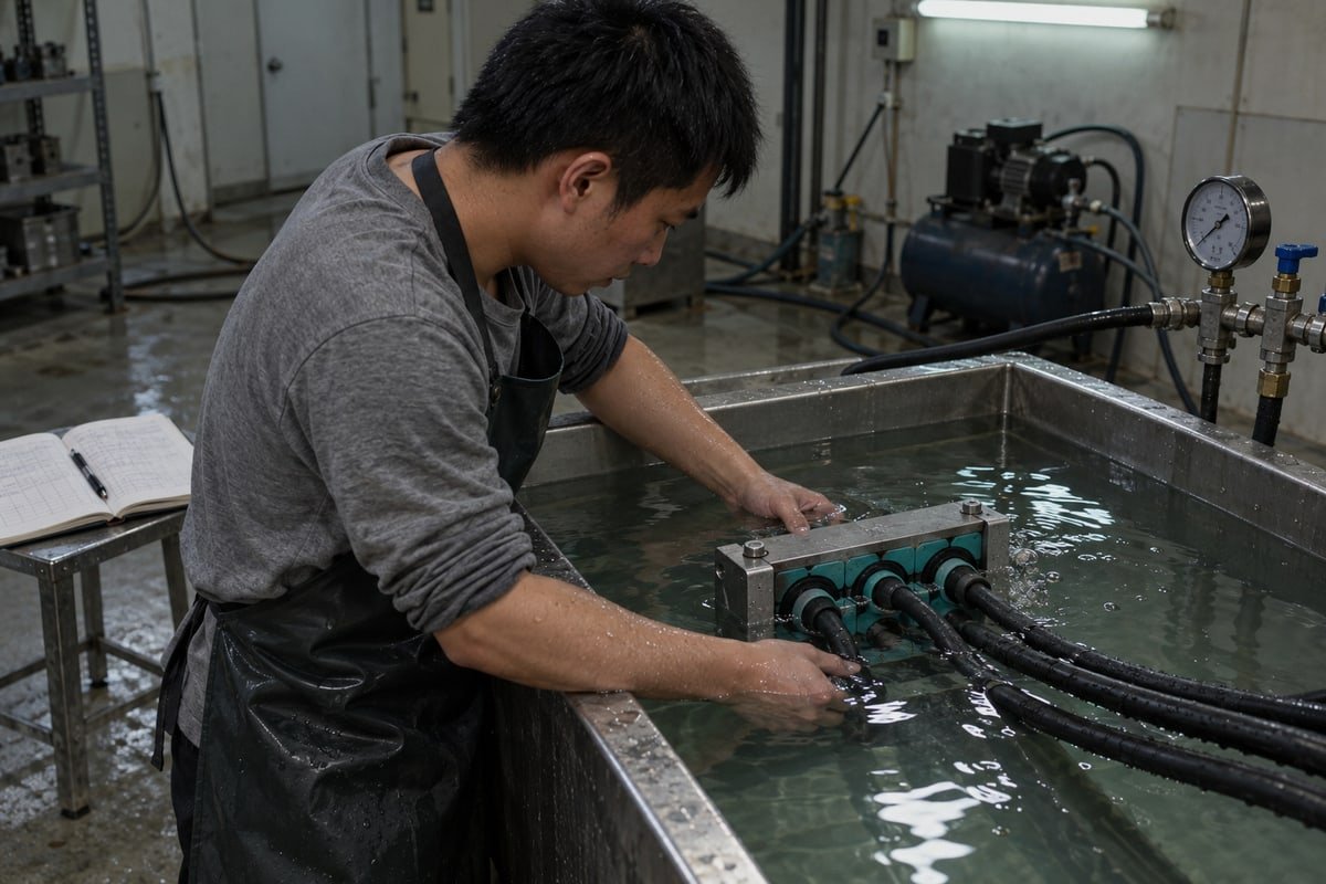
Verification has two layers. The first is configuration: does what is on the wall match what was tested? The second is performance: does this specific installation hold? I treat them separately because a passed leak test on the wrong configuration still fails an audit.
Configuration check against the certificate
Our test documents cover a defined combination of frame, module material, stayplates, and compression unit. Confirm that the installed parts match that combination, including any blank modules. Then confirm torque. Put a calibrated torque wrench 2 on each compression bolt and check that it does not turn further at the specified value. This is a check, not a re-tighten, so do not add torque if the bolt is already at spec. Visually confirm even bulge on the module edges and confirm that no cable sits between module halves at an angle.
Ingress protection rating and pressure-tight seal integrity
An IP68 ingress protection rating 3 and a watertight or gas-tight rating from 0.01 to 0.4 MPa describe the design's capability. On site, you prove pressure-tight seal integrity with a method that suits the location. A pressure test with soap solution on the far side works where the compartment can be pressurised. Where it cannot, ultrasonic leak detection 4 offers a non-destructive alternative that picks up the hiss of gas moving through a micro-gap. Record the method, the pressure or sensitivity, and the result. Skeptical auditors want the log, not the assurance.
Fire-rated cable penetration and long-term maintenance
A fire-rated cable penetration 5 at A-0 or A-60 depends on full packing and correct compression, because gaps become flame paths. Verify that every empty slot holds a blank module, not air. Then plan for time. Cable jackets creep and cold-flow, so compression can relax. Set a torque verification schedule based on your jacket materials and operating temperature, and audit chemical compatibility between the EPDM and any site chemicals to avoid environmental stress cracking. Some operators are now trialling compression wedges with embedded sensors for real-time tension monitoring; the principle is sound, but the sensor still reports against a torque and compression value that comes from the installation sheet.
| Requirement | On-site verification method | Evidence to file |
|---|---|---|
| IP68 | Pressure or soap test, or ultrasonic detection | Test log with method and result |
| Watertight/gas-tight 0.01–0.4 MPa | Pressurised compartment test where feasible | Pressure, duration, observer |
| A-0/A-60 fire rating | Full packing check, blank modules, correct configuration | Filling plan signed against certificate |
| Torque compliance | Calibrated wrench check at spec, no further turn | Wrench calibration record, values |
Conclusion
A multi cable transit leaks or holds on details: module order, lubrication, even torque. Follow the manufacturer's sheet, verify with tests, and qualify a compatible second source with samples.
Footnotes
1. Technical overview of EPDM rubber properties and its common industrial applications. ↩︎
2. NIST is the authoritative body for measurement standards and calibration protocols in the United States. ↩︎
3. Official IEC page explaining the IP rating system for electrical equipment enclosures. ↩︎
4. Explanation of ultrasonic technology used for identifying leaks in pressurized systems. ↩︎
5. International Maritime Organization standards for fire protection and safety on ships. ↩︎



 English
 Español de México
 Deutsch
 Français
 العربية
 Русский